3台のルータでスタティックルートを使用する
※ 前の「シナリオ」の続きとして記載しています。
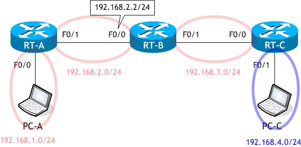
想定するネットワーク構成図
以下の図のように、RT-C を既存のネットワークに追加します。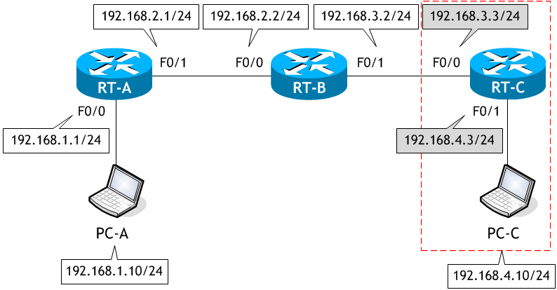
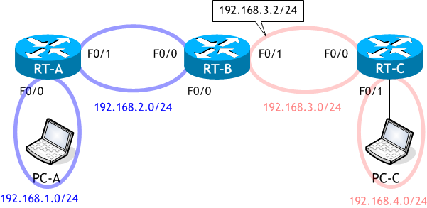
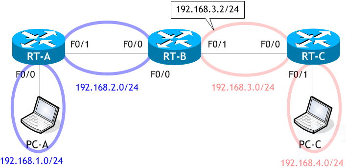
ラボ・シナリオで使用するネットワーク構成図
・前のシナリオで RT-B に接続していた PC-B を RT-C に接続変更し、PC-C とする。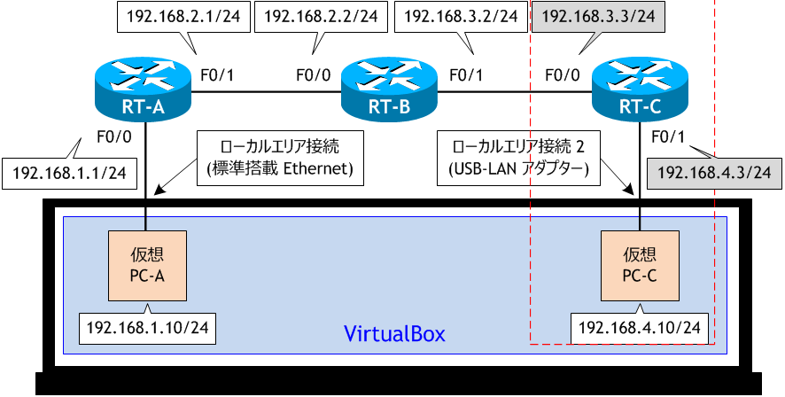
参考 : VirtualBox のインストールと基本的な使用方法
- 追加した RT-C をネットワーク構成図に示す通り設定しなさい。
- RT-C で、192.168.1.0/24、192.168.2.0/24 のネットワークにパケットを転送するために必要なスタティックルートを設定しなさい。
- PC-A から RT-C の F0/1 へ ping を実行しなさい。
- RT-A に、192.168.4.0/24 のためのルート情報を追加設定しなさい。
- RT-B に、192.168.4.0/24 のためのルート情報を追加設定しなさい。
- PC-A から RT-C の F0/1 へ ping を実行しなさい。
- RT-A、RT-B、RT-C それぞれのルーティングテーブルを確認しなさい。
< RT-C >
Router# conf t
Enter configuration commands, one per line.  End with CNTL/Z.
Router(config)# host RT-C
RT-C(config)# int f0/0
RT-C(config-if)# ip add 192.168.3.3 255.255.255.0
RT-C(config-if)# no shut
RT-C(config-if)# int f0/1
RT-C(config-if)# ip add 192.168.4.3 255.255.255.0
RT-C(config-if)# no shut
RT-C(config-if)# ^Z
RT-C#
RT-C はインターフェイスにIPアドレスを設定することにより、192.168.3.0/24 と 192.168.4.0/24 のネットワークは知っていますが、192.168.1.0/24、192.168.2.0/24 のネットワークは知りません。そのため、これらのネットワーク宛のパケットをそのネットワークに届けることができません。そのため、スタティックルートでこの知らないネットワークを RT-C に設定します。
ip route 192.168.1.0 255.255.255.0 192.168.3.2
ip route 192.168.2.0 255.255.255.0 192.168.3.2
ip route 192.168.1.0 255.255.255.0 192.168.3.2
ip route 192.168.2.0 255.255.255.0 192.168.3.2
< RT-C >
RT-C# conf t
Enter configuration commands, one per line.  End with CNTL/Z.
RT-C(config)# ip route 192.168.1.0 255.255.255.0 192.168.3.2
RT-C(config)# ip route 192.168.2.0 255.255.255.0 192.168.3.2
RT-C(config)# ^Z
RT-C#
< PC-A >
C:\> ping 192.168.4.3

192.168.4.3 に ping を送信しています 32 バイトのデータ:
192.168.1.1 からの応答: 宛先ホストに到達できません。
192.168.1.1 からの応答: 宛先ホストに到達できません。
192.168.1.1 からの応答: 宛先ホストに到達できません。
192.168.1.1 からの応答: 宛先ホストに到達できません。

192.168.4.3 の ping 統計:
    パケット数: 送信 = 4、受信 = 4、損失 = 0 (0% の損失)、

C:\>
ping は失敗しました。
これは、既存のネットワークに RT-C を追加することにより新しくできた 192.168.4.0/24 のネットワークを RT-A が知らないからです。そのため、RT-A は PC-A から受け取った 192.168.4.3 宛てのパケットを、そのネットワーク宛に送ることができず ping に失敗したわけです。
これと同様 に RT-B も 192.168.4.0/24 のネットワークを知らないため、RT-A、RT-B それぞれにこれらのネットワークのためのスタティックルートを設定してあげる必要があります。

これは、既存のネットワークに RT-C を追加することにより新しくできた 192.168.4.0/24 のネットワークを RT-A が知らないからです。そのため、RT-A は PC-A から受け取った 192.168.4.3 宛てのパケットを、そのネットワーク宛に送ることができず ping に失敗したわけです。

これと同様 に RT-B も 192.168.4.0/24 のネットワークを知らないため、RT-A、RT-B それぞれにこれらのネットワークのためのスタティックルートを設定してあげる必要があります。

< RT-A >
RT-A# conf t
Enter configuration commands, one per line.  End with CNTL/Z.
RT-A(config)# ip route 192.168.4.0 255.255.255.0 192.168.2.2
RT-A(config)# ^Z
RT-A#
< RT-B >
RT-B# conf t
Enter configuration commands, one per line.  End with CNTL/Z.
RT-B(config)# ip route 192.168.4.0 255.255.255.0 192.168.3.3
RT-B(config)# ^Z
RT-B#
< PC-A >
C:\> ping 192.168.4.3

192.168.4.3 に ping を送信しています 32 バイトのデータ:
192.168.4.3 からの応答: バイト数 =32 時間 =1ms TTL=253
192.168.4.3 からの応答: バイト数 =32 時間 =1ms TTL=253
192.168.4.3 からの応答: バイト数 =32 時間 =1ms TTL=253
192.168.4.3 からの応答: バイト数 =32 時間 =1ms TTL=253

192.168.4.3 の ping 統計:
    パケット数: 送信 = 4、受信 = 4、損失 = 0 (0% の損失)、
ラウンド トリップの概算時間 (ミリ秒):
    最小 = 1ms、最大 = 1ms、平均 = 1ms

C:\>
ping は成功しました。
スタッティックルートではこのように、ネットワーク内のルータが増えれば増えるほど設定しなければならない内容が増えていきます。また、ネットワーク構築後、後からルータが追加された時や、ネットワーク内からルータを取り除いた時には、ネットワーク内の全てのルータのスタティックルートの設定を変更しなければいけません。そのため、大規模ネットワークでは管理コスト (ルータを管理するための手間) が膨大になります。したがって、非常に小規模なネットワークや特定の用途でしかスタティックルーティングは使われません。
スタッティックルートではこのように、ネットワーク内のルータが増えれば増えるほど設定しなければならない内容が増えていきます。また、ネットワーク構築後、後からルータが追加された時や、ネットワーク内からルータを取り除いた時には、ネットワーク内の全てのルータのスタティックルートの設定を変更しなければいけません。そのため、大規模ネットワークでは管理コスト (ルータを管理するための手間) が膨大になります。したがって、非常に小規模なネットワークや特定の用途でしかスタティックルーティングは使われません。
< RT-A >
RT-A# sh ip route | begin Gateway
Gateway of last resort is not set

      192.168.1.0/24 is variably subnetted, 2 subnets, 2 masks
C        192.168.1.0/24 is directly connected, FastEthernet0/0
L        192.168.1.1/32 is directly connected, FastEthernet0/0
      192.168.2.0/24 is variably subnetted, 2 subnets, 2 masks
C        192.168.2.0/24 is directly connected, FastEthernet0/1
L        192.168.2.1/32 is directly connected, FastEthernet0/1
S     192.168.3.0/24 [1/0] via 192.168.2.2  ← 192.168.3.0/24 宛てのルート
S     192.168.4.0/24 [1/0] via 192.168.2.2  ← 192.168.4.0/24 宛てのルート
RT-A#
< RT-B >
RT-B# sh ip route | begin Gateway
Gateway of last resort is not set

S     192.168.1.0/24 [1/0] via 192.168.2.1  ← 192.168.1.0/24 宛てのルート
      192.168.2.0/24 is variably subnetted, 2 subnets, 2 masks
C        192.168.2.0/24 is directly connected, FastEthernet0/0
L        192.168.2.2/32 is directly connected, FastEthernet0/0
      192.168.3.0/24 is variably subnetted, 2 subnets, 2 masks
C        192.168.3.0/24 is directly connected, FastEthernet0/1
L        192.168.3.2/32 is directly connected, FastEthernet0/1
S     192.168.4.0/24 [1/0] via 192.168.3.3  ← 192.168.4.0/24 宛てのルート
RT-B#
< RT-C >
RT-C# sh ip route | begin Gateway
Gateway of last resort is not set

S     192.168.1.0/24 [1/0] via 192.168.3.2  ← 192.168.1.0/24 宛てのルート
S     192.168.2.0/24 [1/0] via 192.168.3.2  ← 192.168.2.0/24 宛てのルート
      192.168.3.0/24 is variably subnetted, 2 subnets, 2 masks
C        192.168.3.0/24 is directly connected, FastEthernet0/0
L        192.168.3.3/32 is directly connected, FastEthernet0/0
      192.168.4.0/24 is variably subnetted, 2 subnets, 2 masks
C        192.168.4.0/24 is directly connected, FastEthernet0/1
L        192.168.4.3/32 is directly connected, FastEthernet0/1
RT-C#