VLSMネットワークでスタティックルートを使用する
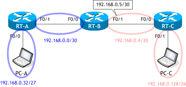
ネットワーク構成図のアドレッシングは VLSM を使用しています。よく「VLSM を使用するなら、OSPF や EIGRP を使わなければいけないのではないか?」と思われている人もいますが、それはダイナミックルーティングを使うなら VLSM に対応したルーティングプロトコルを使わなければならないのであって、スタッティックルーティングには関係ありません。
標準のサブネッティング (サブネット化) は、FLSM (Fixed Length Subnet Mask:固定長サブネットマスク) を使用し、全てのサブネットで同一のサブネットマスクを用いて1つのネットワークを複数のネットワークに分割しますが、VLSM (Variable Length Subnet Mask:可変長サブネットマスク) では、複数の長さのサブネットマスクを用いて1つのネットワークを複数のネットワークに分割します。
簡単に言えば、1つのフロアーをパーティションを使って複数の部屋に分ける時、同じサイズの部屋にしか分けられないか、各部屋に入る人数に合わせてサイズの異なる部屋に分けられるかの違いです。当然、サイズの異なる部屋に分けられた方が効率的ですよね?
そのため、VLSM を使用した方が効率的にネットワークを分割できます。ただし、ルーティングプロトコルを使用する場合は、クラスレスルーティングプロトコル (RIPv2、OSPF、EIGRP など) を使う必要があります。
※ 現実的には、VLSM を使うのはプロバイダくらいで、企業内では使用しません。プライベートアドレスを使用すれば、IPアドレスをちまちま分けなくても膨大に使用できますので、どのプライベートアドレスを使用しても第4オクテット目をホスト用に割り当てるのが一般的です。
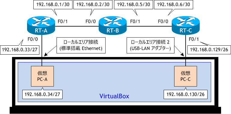
・PC-A は物理 PC に標準搭載している LAN ポートを使用するように VirtualBox を設定する。
・物理 PC に USB-LAN 変換ケーブルを1つ接続し、PC-C がそれを使用するように VirtualBox を設定する。
参考 : VirtualBox のインストールと基本的な使用方法
標準のサブネッティング (サブネット化) は、FLSM (Fixed Length Subnet Mask:固定長サブネットマスク) を使用し、全てのサブネットで同一のサブネットマスクを用いて1つのネットワークを複数のネットワークに分割しますが、VLSM (Variable Length Subnet Mask:可変長サブネットマスク) では、複数の長さのサブネットマスクを用いて1つのネットワークを複数のネットワークに分割します。
簡単に言えば、1つのフロアーをパーティションを使って複数の部屋に分ける時、同じサイズの部屋にしか分けられないか、各部屋に入る人数に合わせてサイズの異なる部屋に分けられるかの違いです。当然、サイズの異なる部屋に分けられた方が効率的ですよね?
そのため、VLSM を使用した方が効率的にネットワークを分割できます。ただし、ルーティングプロトコルを使用する場合は、クラスレスルーティングプロトコル (RIPv2、OSPF、EIGRP など) を使う必要があります。
※ 現実的には、VLSM を使うのはプロバイダくらいで、企業内では使用しません。プライベートアドレスを使用すれば、IPアドレスをちまちま分けなくても膨大に使用できますので、どのプライベートアドレスを使用しても第4オクテット目をホスト用に割り当てるのが一般的です。
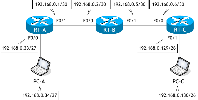
想定するネットワーク構成図

ラボ・シナリオで使用するネットワーク構成図
・物理 PC の VirtualBox 上に、PC-A、PC-C の2つの仮想 PC を構成する。・PC-A は物理 PC に標準搭載している LAN ポートを使用するように VirtualBox を設定する。
・物理 PC に USB-LAN 変換ケーブルを1つ接続し、PC-C がそれを使用するように VirtualBox を設定する。

参考 : VirtualBox のインストールと基本的な使用方法
- RT-A、RT-B、RT-C をネットワーク構成図に示す通り設定しなさい。
- RT-A に適切なスタティックルートの設定をしなさい。
- RT-B に適切なスタティックルートの設定をしなさい。
- RT-C に適切なスタティックルートの設定をしなさい。
- PC-A、PC-C をネットワーク構成図に示す通り設定しなさい。
- RT-A のルーティングテーブルを表示させなさい。
- RT-B のルーティングテーブルを表示させなさい。
- RT-C のルーティングテーブルを表示させなさい。
- PC-A から PC-C へ TraceRoute を実行しなさい。
- RT-A から PC-C へ TraceRoute を実行しなさい。
< RT-A >
Router# conf t
Enter configuration commands, one per line.  End with CNTL/Z.
Router(config)# host RT-A
RT-A(config)# int f0/0
RT-A(config-if)# ip add 192.168.0.33 255.255.255.224
RT-A(config-if)# no shut
RT-A(config-if)# int f0/1
RT-A(config-if)# ip add 192.168.0.1 255.255.255.252
RT-A(config-if)# no shut
RT-A(config-if)# ^Z
RT-A#
< RT-B >
Router# conf t
Enter configuration commands, one per line.  End with CNTL/Z.
Router(config)# host RT-B
RT-B(config)# int f0/0
RT-B(config-if)# ip add 192.168.0.2 255.255.255.252
RT-B(config-if)# no shut
RT-B(config-if)# int f0/1
RT-B(config-if)# ip add 192.168.0.5 255.255.255.252
RT-B(config-if)# no shut
RT-B(config-if)# ^Z
RT-B#
< RT-C >
Router# conf t
Enter configuration commands, one per line.  End with CNTL/Z.
Router(config)# host RT-C
RT-C(config)# int f0/0
RT-C(config-if)# ip add 192.168.0.6 255.255.255.252
RT-C(config-if)# no shut
RT-C(config-if)# int f0/1
RT-C(config-if)# ip add 192.168.0.129 255.255.255.192
RT-C(config-if)# no shut
RT-C(config-if)# ^Z
RT-C#
< RT-A >
RT-A# conf t
Enter configuration commands, one per line.  End with CNTL/Z.
RT-A(config)# ip route 192.168.0.4 255.255.255.252 192.168.0.2
RT-A(config)# ip route 192.168.0.128 255.255.255.192 192.168.0.2
RT-A(config)# ^Z
RT-A#
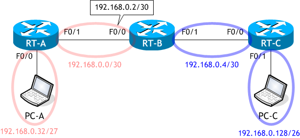
RT-A は、192.168.0.32/27 と 19.168.0.0/30 のネットワークは知っていますが、192.168.0.4/30、192.168.0.128/26 のネットワークは知りませんので、この知らないネットワークをスタティックルートで設定してあげる必要があります。

< RT-B >
RT-B# conf t
Enter configuration commands, one per line.  End with CNTL/Z.
RT-B(config)# ip route 192.168.0.32 255.255.255.224 192.168.0.1
RT-B(config)# ip route 192.168.0.128 255.255.255.192 192.168.0.6
RT-B(config)# ^Z
RT-B#
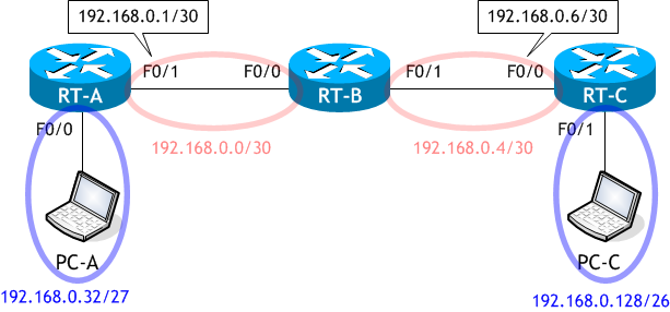
RT-B は、192.168.0.0/30、192.168.0.4/30 のネットワークは知っていますが、192.168.0.32/27 と192.168.0.128/26 のネットワークは知りませんので、この知らないネットワークをスタティックルートで設定してあげる必要があります。

< RT-C >
RT-C# conf t
Enter configuration commands, one per line.  End with CNTL/Z.
RT-C(config)# ip route 192.168.0.32 255.255.255.224 192.168.0.5
RT-C(config)# ip route 192.168.0.0 255.255.255.252 192.168.0.5
RT-C(config)# ^Z
RT-C#
RT-C は、192.168.0.4/30 と 19.168.0.128/26 のネットワークは知っていますが、192.168.0.32/27、192.168.0.0/30 のネットワークは知りませんので、この知らないネットワークをスタティックルートで設定してあげる必要があります。

< PC-A >
C:\> netsh interface ipv4 set address "イーサネット" static 192.168.0.34 255.255.255.224 192.168.0.33

C:\> ipconfig

Windows IP 構成

イーサネット アダプター イーサネット:

   接続固有の DNS サフィックス . . . . .:
   IPv4 アドレス . . . . . . . . . . . .: 192.168.0.34
   サブネット マスク . . . . . . . . . .: 255.255.255.224
   デフォルト ゲートウェイ . . . . . . .: 192.168.0.33

C:\>
< PC-C >
C:\> netsh interface ipv4 set address "イーサネット" static 192.168.0.130 255.255.255.192 192.168.0.129

C:\> ipconfig

Windows IP 構成

イーサネット アダプター イーサネット:

   接続固有の DNS サフィックス . . . . .:
   IPv4 アドレス . . . . . . . . . . . .: 192.168.0.130
   サブネット マスク . . . . . . . . . .: 255.255.255.192
   デフォルト ゲートウェイ . . . . . . .: 192.168.0.129

C:\>
全ての PC は ping 着信許可の設定を行っているものとします。
< RT-A >
RT-A# sh ip route | begin Gateway
Gateway of last resort is not set

      192.168.0.0/24 is variably subnetted, 6 subnets, 4 masks
C        192.168.0.0/30 is directly connected, FastEthernet0/1
L        192.168.0.1/32 is directly connected, FastEthernet0/1
S        192.168.0.4/30 [1/0] via 192.168.0.2
C        192.168.0.32/27 is directly connected, FastEthernet0/0
L        192.168.0.33/32 is directly connected, FastEthernet0/0
S        192.168.0.128/26 [1/0] via 192.168.0.2
RT-A#
IPアドレスを設定した2つのインターフェイスに関するルート情報、スタティックルートで設定した2つのルート情報が RT-A のルーティングテーブルにあります。
< RT-B >
RT-B# sh ip route | begin Gateway
Gateway of last resort is not set

      192.168.0.0/24 is variably subnetted, 6 subnets, 4 masks
C        192.168.0.0/30 is directly connected, FastEthernet0/0
L        192.168.0.2/32 is directly connected, FastEthernet0/0
C        192.168.0.4/30 is directly connected, FastEthernet0/1
L        192.168.0.5/32 is directly connected, FastEthernet0/1
S        192.168.0.32/27 [1/0] via 192.168.0.1
S        192.168.0.128/26 [1/0] via 192.168.0.6
RT-B#
IPアドレスを設定した2つのインターフェイスに関するルート情報、スタティックルートで設定した2つのルート情報が RT-B のルーティングテーブルにあります。
< RT-C >
RT-C# sh ip route | begin Gateway
Gateway of last resort is not set

      192.168.0.0/24 is variably subnetted, 6 subnets, 4 masks
S        192.168.0.0/30 [1/0] via 192.168.0.5
C        192.168.0.4/30 is directly connected, FastEthernet0/0
L        192.168.0.6/32 is directly connected, FastEthernet0/0
S        192.168.0.32/27 [1/0] via 192.168.0.5
C        192.168.0.128/26 is directly connected, FastEthernet0/1
L        192.168.0.129/32 is directly connected, FastEthernet0/1
RT-C#
IPアドレスを設定した2つのインターフェイスに関するルート情報、スタティックルートで設定した2つのルート情報が RT-C のルーティングテーブルにあります。
< PC-A >
C:\> tracert 192.168.0.130

192.168.0.130 へのルートをトレースしています。経由するホップ数は最大 30 です

  1     2 ms     1 ms     1 ms  192.168.0.33   ← RT-A の F0/0
  2     1 ms     1 ms     1 ms  192.168.0.2    ← RT-B の F0/0
  3     1 ms     1 ms     1 ms  192.168.0.6    ← RT-C の F0/0
  4     4 ms     2 ms     1 ms  192.168.0.130  ← PC-C

トレースを完了しました。

C:\>
Windows での TraceRoute のコマンドは tracert です。
< RT-A >
RT-A# traceroute 192.168.0.130
Type escape sequence to abort.
Tracing the route to 192.168.0.130
VRF info: (vrf in name/id, vrf out name/id)
  1 192.168.0.2 0 msec 0 msec 0 msec     ← RT-B の F0/0
  2 192.168.0.6 4 msec 0 msec 0 msec     ← RT-C の F0/0
  3 192.168.0.130 0 msec 0 msec 0 msec   ← PC-C
RT-A#
Cisco ルータの TraceRoute のためのコマンドは traceroute です。
ただし、ほとんどの場合、省略して trace だけで実行します。
ただし、ほとんどの場合、省略して trace だけで実行します。
RT-A# trace?
traceroute