VTPサーバー同士のスイッチ間接続によるVTPの動作を確認する
※ 前の「シナリオ」の続きとして記載しています。
ネットワーク構成図
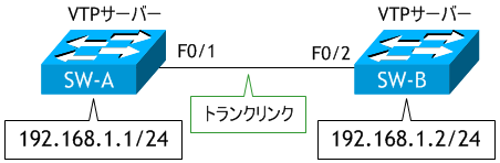
- SW-A に 192.168.1.1/24 を設定しなさい。
- SW-A で、show vtp status コマンドを実行しなさい。
- SW-B に 192.168.1.2/24 を設定しなさい。
- SW-B で、show vtp status コマンドを実行しなさい。
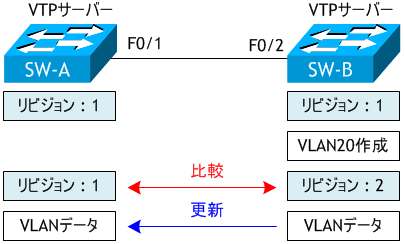
- SW-B で VLAN20 を作成しなさい。
- SW-B で、show vtp status コマンドを実行しなさい。
- SW-A で、show vtp status コマンドを実行しなさい。
- SW-A で VLAN30 を作成しなさい。
- SW-A で、show vtp status コマンドを実行しなさい。
- SW-B で、show vtp status コマンドを実行しなさい。
- SW-A と SW-B の vlan.dat を削除しなさい。
< SW-A >
SW-A# conf t
Enter configuration commands, one per line.  End with CNTL/Z.
SW-A(config)# int vlan 1
SW-A(config-if)# ip add 192.168.1.1 255.255.255.0
SW-A(config-if)# no shut
SW-A(config-if)# ^Z
SW-A#
< SW-A >
SW-A# sh vtp status
VTP Version capable             : 1 to 3
VTP version running             : 1
VTP Domain Name                 : cisco
VTP Pruning Mode                : Disabled
VTP Traps Generation            : Disabled
Device ID                       : 0024.900a.0000
Configuration last modified by 0.0.0.0 at 3-1-93 00:09:55
Local updater ID is 192.168.1.1 on interface Vl1 (lowest numbered VLAN interface found)

Feature VLAN:
--------------
VTP Operating Mode                : Server
Maximum VLANs supported locally   : 255
Number of existing VLANs          : 6
Configuration Revision            : 1
MD5 digest                        : 0x39 0x6E 0x18 0x6D 0x1F 0x15 0xD2 0x32
                                    0xFA 0x7F 0x29 0x73 0x98 0x91 0xFC 0x52
SW-A#
管理 VLAN にIPアドレスを変更すると、Local updater ID が変わります。また、SW-A の VTP Operating Mode は Server です。
< SW-B >
SW-B# conf t
Enter configuration commands, one per line.  End with CNTL/Z.
SW-B(config)# int vlan 1
SW-B(config-if)# ip add 192.168.1.2 255.255.255.0
SW-B(config-if)# no shut
SW-B(config-if)# ^Z
SW-B#
< SW-B >
SW-B# sh vtp status
VTP Version capable             : 1 to 3
VTP version running             : 1
VTP Domain Name                 : cisco
VTP Pruning Mode                : Disabled
VTP Traps Generation            : Disabled
Device ID                       : 0024.900b.0000
Configuration last modified by 0.0.0.0 at 3-1-93 00:09:55
Local updater ID is 192.168.1.2 on interface Vl1 (lowest numbered VLAN interface found)

Feature VLAN:
--------------
VTP Operating Mode                : Server
Maximum VLANs supported locally   : 1005
Number of existing VLANs          : 6
Configuration Revision            : 1
MD5 digest                        : 0x39 0x6E 0x18 0x6D 0x1F 0x15 0xD2 0x32
                                    0xFA 0x7F 0x29 0x73 0x98 0x91 0xFC 0x52
SW-B#
SW-B の Local updater ID も変わりました。また、SW-B の VTP Operating Mode も Server です。
< SW-B >
SW-B# conf t
Enter configuration commands, one per line.  End with CNTL/Z.
SW-B(config)# vlan 20  ← VLAN20 の作成
SW-B(config-vlan)# ^Z
SW-B#
< SW-B >
SW-B# sh vtp status
VTP Version capable             : 1 to 3
VTP version running             : 1
VTP Domain Name                 : cisco
VTP Pruning Mode                : Disabled
VTP Traps Generation            : Disabled
Device ID                       : 0024.900b.0000
Configuration last modified by 192.168.1.2 at 3-1-93 00:15:14
Local updater ID is 192.168.1.2 on interface Vl1 (lowest numbered VLAN interface found)

Feature VLAN:
--------------
VTP Operating Mode                : Server
Maximum VLANs supported locally   : 1005
Number of existing VLANs          : 7
Configuration Revision            : 2
MD5 digest                        : 0xA9 0x9C 0x04 0x7A 0xF0 0x06 0xB6 0xCB
                                    0x1D 0x52 0xFA 0x3A 0x95 0xB1 0xA1 0xD7
SW-B#
< SW-A >
SW-A# sh vtp status
VTP Version capable             : 1 to 3
VTP version running             : 1
VTP Domain Name                 : cisco
VTP Pruning Mode                : Disabled
VTP Traps Generation            : Disabled
Device ID                       : 0024.900a.0000
Configuration last modified by 192.168.1.2 at 3-1-93 00:15:14
Local updater ID is 192.168.1.1 on interface Vl1 (lowest numbered VLAN interface found)

Feature VLAN:
--------------
VTP Operating Mode                : Server
Maximum VLANs supported locally   : 255
Number of existing VLANs          : 7
Configuration Revision            : 2
MD5 digest                        : 0xA9 0x9C 0x04 0x7A 0xF0 0x06 0xB6 0xCB
                                    0x1D 0x52 0xFA 0x3A 0x95 0xB1 0xA1 0xD7
SW-A#
Configuration last modified by 192.168.1.2
各スイッチにIPアドレスを設定することにより、どのスイッチで更新された (最後に編集された) VLAN データに同期しているかがわかります。192.168.1.2 は SW-B のIPアドレスですので、SW-B の VLAN データに同期しています。SW-B に VLAN20 を作成することにより、SW-B のコンフィグレーションリビジョン番号が 1 → 2 へと up し、コンフィグレーションリビジョン番号が 1 の SW-A の VLAN データが SW-B の VLAN データにより更新されたわけです。
< SW-A >
SW-A# conf t
Enter configuration commands, one per line.  End with CNTL/Z.
SW-A(config)# vlan 30  ← VLAN30 の作成
SW-A(config-vlan)# ^Z
SW-A#
< SW-A >
SW-A# sh vtp status
VTP Version capable             : 1 to 3
VTP version running             : 1
VTP Domain Name                 : cisco
VTP Pruning Mode                : Disabled
VTP Traps Generation            : Disabled
Device ID                       : 0024.900a.0000
Configuration last modified by 192.168.1.1 at 3-1-93 00:19:11
Local updater ID is 192.168.1.1 on interface Vl1 (lowest numbered VLAN interface found)

Feature VLAN:
--------------
VTP Operating Mode                : Server
Maximum VLANs supported locally   : 255
Number of existing VLANs          : 8
Configuration Revision            : 3
MD5 digest                        : 0xDB 0x89 0x0C 0x23 0x27 0x10 0x35 0xEA
                                    0x34 0x03 0x9A 0x41 0x39 0xE3 0x8E 0xA9
SW-A#
< SW-B >
SW-B# sh vtp status
VTP Version capable             : 1 to 3
VTP version running             : 1
VTP Domain Name                 : cisco
VTP Pruning Mode                : Disabled
VTP Traps Generation            : Disabled
Device ID                       : 0024.900b.0000
Configuration last modified by 192.168.1.1 at 3-1-93 00:19:11
Local updater ID is 192.168.1.2 on interface Vl1 (lowest numbered VLAN interface found)

Feature VLAN:
--------------
VTP Operating Mode                : Server
Maximum VLANs supported locally   : 1005
Number of existing VLANs          : 8
Configuration Revision            : 3
MD5 digest                        : 0xDB 0x89 0x0C 0x23 0x27 0x10 0x35 0xEA
                                    0x34 0x03 0x9A 0x41 0x39 0xE3 0x8E 0xA9
SW-B#
Configuration last modified by 192.168.1.1
192.168.1.1 は SW-A のIPアドレスですので、SW-A の VLAN データに同期しています。SW-A に VLAN30 を作成することにより、SW-A のコンフィグレーションリビジョン番号が 2 → 3 へと up し、コンフィグレーションリビジョン番号が 2 の SW-B の VLAN データが SW-A の VLAN データにより更新されました。

SW-A、SW-B ともに VTPサーバーであるため、どちらのスイッチでも VLAN の作成/削除が可能で、最後に VLAN データベースを編集したスイッチの VLAN データにドメイン内の全てのスイッチが同期します。VTP モードのデフォルトは Server です。
< SW-A >
SW-A# delete flash:vlan.dat
Delete filename [vlan.dat]? < Enter >
Delete flash:vlan.dat? [confirm] < Enter >
SW-A#
< SW-B >
SW-B# delete flash:vlan.dat
Delete filename [vlan.dat]? < Enter >
Delete flash:vlan.dat? [confirm] < Enter >
SW-B#