フレームリレーを設定する (ハブ & スポーク)
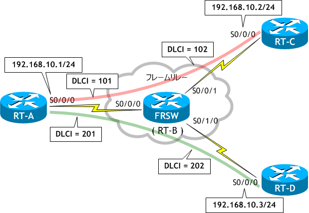
ネットワーク構成図

- RT-B に FRSW という名前を付け、ネットワーク構成図を参考に、フレームリレースイッチとして構成しなさい。
- ネットワーク構成図に従い、RT-A、RT-C、RT-D でフレームリレーを構成しなさい。
- 全てのルータ間で ping を実施しなさい。
- RT-A、RT-C、RT-D で sh frame-relay map を実行し、フレームリレーマップを確認しなさい。
- RT-C と RT-D 間で通信ができるように手動でマップエントリを設定しなさい。
- RT-C と RT-D で sh frame-relay map を実行し、フレームリレーマップを確認しなさい。
- RT-C と RT-D 間で ping を実施しなさい。
< RT-B >
Router# conf t
Enter configuration commands, one per line.  End with CNTL/Z.
Router(config)# host FRSW
FRSW(config)# frame-relay switching
FRSW(config)# int s0/0/0
FRSW(config-if)# description to RT-A
FRSW(config-if)# no ip address
FRSW(config-if)# clock rate 64000
FRSW(config-if)# encap frame-relay
FRSW(config-if)# frame-relay intf-type dce
FRSW(config-if)# frame-relay route 101 int s0/0/1 102
FRSW(config-if)# frame-relay route 201 int s0/1/0 202
FRSW(config-if)# no shut
FRSW(config-if)# int s0/0/1
FRSW(config-if)# description to RT-C
FRSW(config-if)# no ip address
FRSW(config-if)# clock rate 64000
FRSW(config-if)# encap frame-relay
FRSW(config-if)# frame-relay intf-type dce
FRSW(config-if)# frame-relay route 102 int s0/0/0 101
FRSW(config-if)# no shut
FRSW(config-if)# int s0/1/0
FRSW(config-if)# description to RT-D
FRSW(config-if)# no ip address
FRSW(config-if)# clock rate 64000
FRSW(config-if)# encap frame-relay
FRSW(config-if)# frame-relay intf-type dce
FRSW(config-if)# frame-relay route 202 int s0/0/0 201
FRSW(config-if)# no shut
FRSW(config-if)# ^Z
FRSW#
フレームリレースイッチの構成は CCNA の範囲外です。
< RT-A >
Router# conf t
Enter configuration commands, one per line.  End with CNTL/Z.
Router(config)# host RT-A
RT-A(config)# int s0/0/0
RT-A(config-if)# ip add 192.168.10.1 255.255.255.0
RT-A(config-if)# encapsulation frame-relay
RT-A(config-if)# no shut
RT-A(config-if)# ^Z
RT-A#
< RT-C >
Router# conf t
Enter configuration commands, one per line.  End with CNTL/Z.
Router(config)# host RT-C
RT-C(config)# int s0/0/0
RT-C(config-if)# ip add 192.168.10.2 255.255.255.0
RT-C(config-if)# encapsulation frame-relay
RT-C(config-if)# no shut
RT-C(config-if)# ^Z
RT-C#
< RT-D >
Router# conf t
Enter configuration commands, one per line.  End with CNTL/Z.
Router(config)# host RT-D
RT-D(config)# int s0/0/0
RT-D(config-if)# ip add 192.168.10.3 255.255.255.0
RT-D(config-if)# encapsulation frame-relay
RT-D(config-if)# no shut
RT-D(config-if)# ^Z
RT-D#
< RT-A >
RT-A# ping 192.168.10.2  ← RT-C への ping
Type escape sequence to abort.
Sending 5, 100-byte ICMP Echos to 192.168.10.2, timeout is 2 seconds:
!!!!!  ← 成功
Success rate is 100 percent (5/5), round-trip min/avg/max = 56/58/60 ms


RT-A# ping 192.168.10.3  ← RT-D への ping
Type escape sequence to abort.
Sending 5, 100-byte ICMP Echos to 192.168.10.3, timeout is 2 seconds:
!!!!!  ← 成功
Success rate is 100 percent (5/5), round-trip min/avg/max = 56/57/60 ms
RT-A#
< RT-C >
RT-C# ping 192.168.10.1  ← RT-A への ping
Type escape sequence to abort.
Sending 5, 100-byte ICMP Echos to 192.168.10.1, timeout is 2 seconds:
!!!!!  ← 成功
Success rate is 100 percent (5/5), round-trip min/avg/max = 56/58/61 ms
RT-C#


RT-C# ping 192.168.10.3  ← RT-D への ping
Type escape sequence to abort.
Sending 5, 100-byte ICMP Echos to 192.168.10.3, timeout is 2 seconds:
.....  ← 失敗
Success rate is 0 percent (0/5)
RT-C#
< RT-D >
RT-D# ping 192.168.10.1  ← RT-A への ping
Type escape sequence to abort.
Sending 5, 100-byte ICMP Echos to 192.168.10.1, timeout is 2 seconds:
!!!!!  ← 成功
Success rate is 100 percent (5/5), round-trip min/avg/max = 56/57/61 ms
RT-D#


RT-D# ping 192.168.10.2  ← RT-C への ping
Type escape sequence to abort.
Sending 5, 100-byte ICMP Echos to 192.168.10.2, timeout is 2 seconds:
.....  ← 失敗
Success rate is 0 percent (0/5)
RT-D#
< RT-A >
RT-A# sh frame-relay map
Serial0/0/0 (up): ip 192.168.10.2 dlci 101(0x65,0x1850), dynamic,  ← RT-C 宛て
              broadcast,, status defined, active
Serial0/0/0 (up): ip 192.168.10.3 dlci 201(0xC9,0x3090), dynamic,  ← RT-D 宛て
              broadcast,
              CISCO, status defined, active
RT-A#
< RT-C >
RT-C# sh frame-relay map
Serial0/0/0 (up): ip 192.168.10.1 dlci 102(0x66,0x1860), dynamic,  ← RT-A 宛て
              broadcast,
              CISCO, status defined, active
RT-C#
< RT-D >
RT-D# sh frame-relay map
Serial0/0/0 (up): ip 192.168.10.1 dlci 202(0xCA,0x30A0), dynamic,  ← RT-A 宛て
              broadcast,, status defined, active
RT-D#
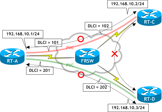
RT-A には、RT-C、RT-D 宛てのマップエントリがありますが、RT-C と RT-D には、RT-A までのマップエントリしかありません。Inverse ARP では 直接 PVC のない RT-C と RT-D 間で通信するためのマップエントリが自動で作成されませんので、frame-relay map コマンドを使って手動で設定する必要があります。
< RT-C >
RT-C# conf t
Enter configuration commands, one per line.  End with CNTL/Z.
RT-C(config)# int s0/0/0
RT-C(config-if)# frame-relay map ip 192.168.10.3 102
RT-C(config-if)# ^Z
RT-C#
< RT-D >
RT-D# conf t
Enter configuration commands, one per line.  End with CNTL/Z.
RT-D(config)# int s0/0/0
RT-D(config-if)# frame-relay map ip 192.168.10.2 202
RT-D(config-if)# ^Z
RT-D#
RT-C、RT-D それぞれに、相手側のルータに行くためのマップエントリを追加しました。
< RT-C >
RT-C# sh frame-relay map
Serial0/0/0 (up): ip 192.168.10.3 dlci 102(0x66,0x1860), static,  ← RT-D 宛て
              CISCO, status defined, active
Serial0/0/0 (up): ip 192.168.10.1 dlci 102(0x66,0x1860), dynamic,
              broadcast,
              CISCO, status defined, active
RT-C#
< RT-D >
RT-D# sh frame-relay map
Serial0/0/0 (up): ip 192.168.10.2 dlci 202(0xCA,0x30A0), static,  ← RT-C 宛て
              CISCO, status defined, active
Serial0/0/0 (up): ip 192.168.10.1 dlci 202(0xCA,0x30A0), dynamic,
              broadcast,, status defined, active
RT-D#
RT-C、RT-D それぞれ、直接 PVC のある RT-A 宛ては Inverse ARP で動的 (dynamic) に生成し、動的に生成できない相手へのルートは RT-A 経由でフレームが送られるように静的 (static) に設定しました。
< RT-C >
RT-C# ping 192.168.10.3
Type escape sequence to abort.
Sending 5, 100-byte ICMP Echos to 192.168.10.3, timeout is 2 seconds:
!!!!!  ← 成功
Success rate is 100 percent (5/5), round-trip min/avg/max = 112/116/124 ms
RT-C#
< RT-D >
RT-D# ping 192.168.10.2
Type escape sequence to abort.
Sending 5, 100-byte ICMP Echos to 192.168.10.2, timeout is 2 seconds:
!!!!!  ← 成功
Success rate is 100 percent (5/5), round-trip min/avg/max = 112/116/124 ms
RT-D#
RT-C と RT-D 間は RT-A 経由で通信していますので、応答に時間がかかります。round-trip を参照。
