フレームリレーを設定する (マルチポイント・サブインターフェイス)
前のシナリオではサブインターフェイスを使用せずにフレームリレーを構成しましたが、フレームリレーではサブインターフェイスを使用することが多いので、サブインターフェイスを使用した設定を行います。
ネットワーク構成図
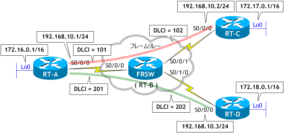
- RT-B に FRSW という名前を付け、ネットワーク構成図を参考に、フレームリレースイッチとして構成しなさい。
- RT-A の S0/0/0 をマルチポイント・サブインターフェイスで構成し、フレームリレーの設定には Inverse ARP を使用しなさい。
- RT-C、RT-D の物理インターフェイス S0/0/0 にフレームリレーを設定しなさい。
- 全てのルータ間で ping を実施しなさい。
- RT-A、RT-C、RT-D で sh frame-relay map を実行し、フレームリレーマップを確認しなさい。
- RT-C と RT-D 間で通信ができるように手動でマップエントリを設定しなさい。
- RT-C と RT-D で sh frame-relay map を実行し、フレームリレーマップを確認しなさい。
- RT-C と RT-D 間で ping を実施しなさい。
- RT-A、RTC、RT-D にループバックインターフェイスの設定をし、EIGRP を構成しなさい。
- RT-A、RTC、RT-D でルーティングテーブルを確認しなさい。
- RT-A でスプリットホライズンを無効にしなさい。
- RT-C と RT-D でルーティングテーブルを確認しなさい。
< RT-B >
Router# conf t
Enter configuration commands, one per line.  End with CNTL/Z.
Router(config)# host FRSW
FRSW(config)# frame-relay switching
FRSW(config)# int s0/0/0
FRSW(config-if)# description to RT-A
FRSW(config-if)# no ip address
FRSW(config-if)# clock rate 64000
FRSW(config-if)# encap frame-relay
FRSW(config-if)# frame-relay intf-type dce
FRSW(config-if)# frame-relay route 101 int s0/0/1 102
FRSW(config-if)# frame-relay route 201 int s0/1/0 202
FRSW(config-if)# no shut
FRSW(config-if)# int s0/0/1
FRSW(config-if)# description to RT-C
FRSW(config-if)# no ip address
FRSW(config-if)# clock rate 64000
FRSW(config-if)# encap frame-relay
FRSW(config-if)# frame-relay intf-type dce
FRSW(config-if)# frame-relay route 102 int s0/0/0 101
FRSW(config-if)# no shut
FRSW(config-if)# int s0/1/0
FRSW(config-if)# description to RT-D
FRSW(config-if)# no ip address
FRSW(config-if)# clock rate 64000
FRSW(config-if)# encap frame-relay
FRSW(config-if)# frame-relay intf-type dce
FRSW(config-if)# frame-relay route 202 int s0/0/0 201
FRSW(config-if)# no shut
FRSW(config-if)# ^Z
FRSW#
フレームリレースイッチの構成は CCNA の範囲外です。
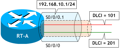
< RT-A >
Router# conf t
Enter configuration commands, one per line.  End with CNTL/Z.
Router(config)# host RT-A
RT-A(config)# int s0/0/0
RT-A(config-if)# no ip add  ← 物理インターフェイスにはIPアドレスは設定しない
RT-A(config-if)# no shut    ← 物理インターフェイスを有効にする
RT-A(config-if)# encap frame-relay        ← 物理インターフェイスにカプセル化タイプを設定する
RT-A(config-if)# int s0/0/0.1 multipoint  ← サブインターフェイスを multipoint で構成する
RT-A(config-subif)# ip add 192.168.10.1 255.255.255.0  ← サブインターフェイスにIPアドレスを設定する
RT-A(config-subif)# frame-relay interface-dlci 101     ← サブインターフェイスで INARP を使用するときに設定する
RT-A(config-fr-dlci)# frame-relay interface-dlci 201   ← サブインターフェイスで INARP を使用するときに設定する
RT-A(config-fr-dlci)# ^Z
RT-A#
物理インターフェイスで no ip add をしていますが、実際には初期状態ではルータにIPアドレスは設定されていませんので、このコマンドは必要ありません。ただし、CCNA の試験的には覚えておいた方がいいので、ここではあえてこのコマンドを実行しています。
マルチポイント・サブインターフェイスで Inverse ARP を使用する場合、frame-relay interface-dlci xxx コマンドでサブインターフェイスに DLCI を関連付ける必要があります。Inverse ARP を使用しない場合はこのコマンドは必要ありませんが、frame-relay map ip コマンドで静的マップエントリを追加する必要があります。
マルチポイント・サブインターフェイスで Inverse ARP を使用する場合、frame-relay interface-dlci xxx コマンドでサブインターフェイスに DLCI を関連付ける必要があります。Inverse ARP を使用しない場合はこのコマンドは必要ありませんが、frame-relay map ip コマンドで静的マップエントリを追加する必要があります。
必ずではなくたまになのですが、frame-relay interface-dlci xxx が以下のようにエラーで設定できない場合があります。
RT-A(config-subif)# frame-relay interface-dlci 101
%PVC already assigned to interface Serial0/0/0
RT-A(config-subif)# frame-relay interface-dlci 201
%PVC already assigned to interface Serial0/0/0
RT-A(config-subif)#
Serial0/0/0 にアサイン済みというエラーなので、LMI でフレームリレースイッチから DLCI を自動取得し、取得した DLCI を物理インターフェイスに関連付けられ、サブインターフェイスへの関連付けができないのではないかと思います。この場合は、物理インターフェイスで no frame-relay interface-dlci xxx コマンドを実行しアサインを解除して、S0/0/0.1 でこれらのコマンド実行すれば設定できます。
RT-A(config-subif)# int s0/0/0
RT-A(config-if)# no frame-relay interface-dlci 101
RT-A(config-if)# no frame-relay interface-dlci 201
RT-A(config-if)# int s0/0/0.1 multipoint
RT-A(config-subif)# frame-relay interface-dlci 101
RT-A(config-fr-dlci)# frame-relay interface-dlci 201
RT-A(config-fr-dlci)# do sh run | section interface Serial0/0/0
interface Serial0/0/0
 no ip address
 encapsulation frame-relay
 frame-relay lmi-type cisco
interface Serial0/0/0.1 multipoint
 ip address 192.168.10.1 255.255.255.0
 frame-relay interface-dlci 101
 frame-relay interface-dlci 201
RT-A(config-fr-dlci)#
< RT-C >
Router# conf t
Enter configuration commands, one per line.  End with CNTL/Z.
Router(config)# host RT-C
RT-C(config)# int s0/0/0
RT-C(config-if)# ip add 192.168.10.2 255.255.255.0
RT-C(config-if)# encap frame-relay
RT-C(config-if)# no shut
RT-C(config-if)# ^Z
RT-C#
< RT-D >
Router# conf t
Enter configuration commands, one per line.  End with CNTL/Z.
Router(config)# host RT-D
RT-D(config)# int s0/0/0
RT-D(config-if)# ip add 192.168.10.3 255.255.255.0
RT-D(config-if)# encap frame-relay
RT-D(config-if)# no shut
RT-D(config-if)# ^Z
RT-D#
RT-C と RT-D は PVC が1つなので前のシナリオと同様に物理インターフェイスにフレームリレーを設定しましたが、マルチポイント・サブインターフェイスや次のシナリオのポイントツーポイント・サブインターフェイスで構成することもできます。ただ、PVC が1つのみであれば、わざわざサブインターフェイスを使用する必要はありません。
< RT-A >
RT-A# ping 192.168.10.2  ← RT-C への ping
Type escape sequence to abort.
Sending 5, 100-byte ICMP Echos to 192.168.10.2, timeout is 2 seconds:
!!!!!  ← 成功
Success rate is 100 percent (5/5), round-trip min/avg/max = 56/58/60 ms


RT-A# ping 192.168.10.3  ← RT-D への ping
Type escape sequence to abort.
Sending 5, 100-byte ICMP Echos to 192.168.10.3, timeout is 2 seconds:
!!!!!  ← 成功
Success rate is 100 percent (5/5), round-trip min/avg/max = 56/57/60 ms
RT-A#
< RT-C >
RT-C# ping 192.168.10.1  ← RT-A への ping
Type escape sequence to abort.
Sending 5, 100-byte ICMP Echos to 192.168.10.1, timeout is 2 seconds:
!!!!!  ← 成功
Success rate is 100 percent (5/5), round-trip min/avg/max = 56/58/61 ms
RT-C#


RT-C# ping 192.168.10.3  ← RT-D への ping
Type escape sequence to abort.
Sending 5, 100-byte ICMP Echos to 192.168.10.3, timeout is 2 seconds:
.....  ← 失敗
Success rate is 0 percent (0/5)
RT-C#
< RT-D >
RT-D# ping 192.168.10.1  ← RT-A への ping
Type escape sequence to abort.
Sending 5, 100-byte ICMP Echos to 192.168.10.1, timeout is 2 seconds:
!!!!!  ← 成功
Success rate is 100 percent (5/5), round-trip min/avg/max = 56/57/61 ms
RT-D#


RT-D# ping 192.168.10.2  ← RT-C への ping
Type escape sequence to abort.
Sending 5, 100-byte ICMP Echos to 192.168.10.2, timeout is 2 seconds:
.....  ← 失敗
Success rate is 0 percent (0/5)
RT-D#
RT-C と RT-D 間で ping が失敗しました。
< RT-A >
RT-A# sh frame-relay map
Serial0/0/0.1 (up): ip 192.168.10.2 dlci 101(0x65,0x1850), dynamic,  ← RT-C 宛て
              broadcast,, status defined, active
Serial0/0/0.1 (up): ip 192.168.10.3 dlci 201(0xC9,0x3090), dynamic,  ← RT-D 宛て
              broadcast,, status defined, active
RT-A#
< RT-C >
RT-C# sh frame-relay map
Serial0/0/0 (up): ip 192.168.10.1 dlci 102(0x66,0x1860), dynamic,    ← RT-A 宛て
              broadcast,
              CISCO, status defined, active
RT-C#
< RT-D >
RT-D# sh frame-relay map
Serial0/0/0 (up): ip 192.168.10.1 dlci 202(0xCA,0x30A0), dynamic,    ← RT-A 宛て
              broadcast,
              CISCO, status defined, active
RT-D#
RT-A には、RT-C、RT-D 宛てのマップエントリがありますが、RT-C と RT-D には、RT-A までのマップエントリしかありません。Inverse ARP では RT-C と RT-D 間で通信するためのマップエントリが自動で作成されませんので、frame-relay map を使って手動で設定する必要があります。
< RT-C >
RT-C# conf t
Enter configuration commands, one per line.  End with CNTL/Z.
RT-C(config)# int s0/0/0
RT-C(config-subif)# frame-relay map ip 192.168.10.3 102 broadcast
RT-C(config-subif)# ^Z
RT-C#
< RT-D >
RT-D# conf t
Enter configuration commands, one per line.  End with CNTL/Z.
RT-D(config)# int s0/0/0
RT-D(config-subif)# frame-relay map ip 192.168.10.2 202 broadcast
RT-D(config-subif)# ^Z
RT-D#
RT-C、RT-D それぞれに、相手側のルータに行くためのマップエントリを追加しました。
broadcast オプションは、この pvc (RT-C は DLCI 102、RT-D は DLCI 202) を使ってブロードキャスト (およびマルチキャスト) を転送する場合に使用します。ルーティングプロトコルのルーティングアップデートは、ブロードキャストやマルチキャストを使いますので、ダイナミックルーティングプロトコルを使用する場合は必要なオプションです。ただし、sh frame-relay map を見て分かるように、このコマンドを実行する前のマップエントリに、この pvc (RT-C は DLCI 102、RT-D は DLCI 202) に既に broadcast オプションが付いていますので、本当はここでは必要ありません。
broadcast オプションは、この pvc (RT-C は DLCI 102、RT-D は DLCI 202) を使ってブロードキャスト (およびマルチキャスト) を転送する場合に使用します。ルーティングプロトコルのルーティングアップデートは、ブロードキャストやマルチキャストを使いますので、ダイナミックルーティングプロトコルを使用する場合は必要なオプションです。ただし、sh frame-relay map を見て分かるように、このコマンドを実行する前のマップエントリに、この pvc (RT-C は DLCI 102、RT-D は DLCI 202) に既に broadcast オプションが付いていますので、本当はここでは必要ありません。
RT-C# sh frame-relay map
Serial0/0/0 (up): ip 192.168.10.1 dlci 102(0x66,0x1860), dynamic,
              broadcast
              CISCO, status defined, active
RT-C#
● 静的マップエントリの作成は絶対に必要か?
フレームリレーでマルチポイント接続をする場合、フレームリレー側インターフェイスの 192.168.10.x のアドレスを使ってスポーク同士で疎通確認をするには今回のように静的マップエントリの作成が必要ですが、内部 LAN のトラフィックの観点から言えば、静的マップエントリの作成をしなくても RT-A でトラフィックをルーティングするので通信は可能です。
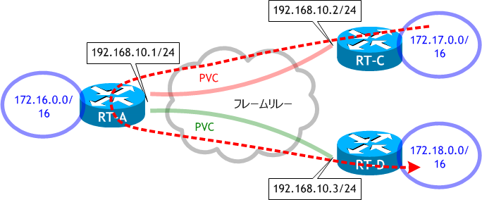
ただし、当然、各ルータにはそれぞれのネットワーク (172.x.x.x) へ行くための適切なルーティングテーブルが必要です。
フレームリレーでマルチポイント接続をする場合、フレームリレー側インターフェイスの 192.168.10.x のアドレスを使ってスポーク同士で疎通確認をするには今回のように静的マップエントリの作成が必要ですが、内部 LAN のトラフィックの観点から言えば、静的マップエントリの作成をしなくても RT-A でトラフィックをルーティングするので通信は可能です。

ただし、当然、各ルータにはそれぞれのネットワーク (172.x.x.x) へ行くための適切なルーティングテーブルが必要です。
< RT-A >
RT-A# sh frame-relay map
Serial0/0/0.1 (up): ip 192.168.10.2 dlci 101(0x65,0x1850), dynamic,  ← RT-C 宛て
              broadcast,, status defined, active
Serial0/0/0.1 (up): ip 192.168.10.3 dlci 201(0xC9,0x3090), dynamic,  ← RT-D 宛て
              broadcast,, status defined, active
RT-A# sh ip route eigrp | begin Gateway
Gateway of last resort is not set

D     172.17.0.0/16 [90/2297856] via 192.168.10.2, 00:54:53, Serial0/0/0.1  ← RT-C 宛て
D     172.18.0.0/16 [90/2297856] via 192.168.10.3, 00:43:44, Serial0/0/0.1  ← RT-D 宛て
RT-A#
< RT-C >
RT-C# sh frame-relay map
Serial0/0/0 (up): ip 192.168.10.1 dlci 102(0x66,0x1860), dynamic,    ← RT-A 宛て
              broadcast,
              CISCO, status defined, active
RT-C# sh ip route eigrp | begin Gateway
Gateway of last resort is not set

D     172.16.0.0/16 [90/2297856] via 192.168.10.1, 00:54:58, Serial0/0/0  ← RT-A 宛て
D     172.18.0.0/16 [90/2809856] via 192.168.10.1, 00:40:56, Serial0/0/0  ← RT-D 宛て
RT-C#
< RT-D >
RT-D# sh frame-relay map
Serial0/0/0 (up): ip 192.168.10.1 dlci 202(0xCA,0x30A0), dynamic,    ← RT-A 宛て
              broadcast,
              CISCO, status defined, active
RT-D# sh ip route eigrp | begin Gateway
Gateway of last resort is not set

D     172.16.0.0/16 [90/2297856] via 192.168.10.1, 00:43:55, Serial0/0/0  ← RT-A 宛て
D     172.17.0.0/16 [90/2809856] via 192.168.10.1, 00:41:01, Serial0/0/0  ← RT-C 宛て
RT-D#
< RT-C >
RT-C# sh frame-relay map
Serial0/0/0 (up): ip 192.168.10.3 dlci 102(0x66,0x1860), static,    ← RT-D 宛て
              broadcast,
              CISCO, status defined, active
Serial0/0/0 (up): ip 192.168.10.1 dlci 102(0x66,0x1860), dynamic,
              broadcast,
              CISCO, status defined, active
RT-C#
< RT-D >
RT-D# sh frame-relay map
Serial0/0/0 (up): ip 192.168.10.2 dlci 202(0xCA,0x30A0), static,    ← RT-C 宛て
              broadcast,
              CISCO, status defined, active
Serial0/0/0 (up): ip 192.168.10.1 dlci 202(0xCA,0x30A0), dynamic,
              broadcast,
              CISCO, status defined, active
RT-D#
設定したマップエントリが追加されています。
< RT-C >
RT-C# ping 192.168.10.3
Type escape sequence to abort.
Sending 5, 100-byte ICMP Echos to 192.168.10.3, timeout is 2 seconds:
!!!!!  ← 成功
Success rate is 100 percent (5/5), round-trip min/avg/max = 112/116/124 ms
RT-C#
< RT-D >
RT-D# ping 192.168.10.2
Type escape sequence to abort.
Sending 5, 100-byte ICMP Echos to 192.168.10.2, timeout is 2 seconds:
!!!!!  ← 成功
Success rate is 100 percent (5/5), round-trip min/avg/max = 112/116/124 ms
RT-D#
< RT-A >
RT-A# conf t
Enter configuration commands, one per line.  End with CNTL/Z.
RT-A(config)# int lo0
RT-A(config-if)# ip add 172.16.0.1 255.255.0.0
RT-A(config-if)# router eigrp 1
RT-A(config-router)# net 192.168.10.0
RT-A(config-router)# net 172.16.0.0
RT-A(config-router)# ^Z
RT-A#
< RT-C >
RT-C# conf t
Enter configuration commands, one per line.  End with CNTL/Z.
RT-C(config)# int lo0
RT-C(config-if)# ip add 172.17.0.1 255.255.0.0
RT-C(config-if)# router eigrp 1
RT-C(config-router)# net 192.168.10.0
RT-C(config-router)# net 172.17.0.0
RT-C(config-router)# ^Z
RT-C#
< RT-D >
RT-D# conf t
Enter configuration commands, one per line.  End with CNTL/Z.
RT-D(config)# int lo0
RT-D(config-if)# ip add 172.18.0.1 255.255.0.0
RT-D(config)# router eigrp 1
RT-D(config-router)# net 192.168.10.0
RT-D(config-router)# net 172.18.0.0
RT-D(config-router)# ^Z
RT-D#
< RT-A >
RT-A# sh ip route eigrp | begin Gateway
Gateway of last resort is not set

D     172.17.0.0/16 [90/2297856] via 192.168.10.2, 00:00:29, Serial0/0/0.1
D     172.18.0.0/16 [90/2297856] via 192.168.10.3, 00:00:21, Serial0/0/0.1
RT-A#
< RT-C >
RT-C# sh ip route eigrp | begin Gateway
Gateway of last resort is not set

D     172.16.0.0/16 [90/2297856] via 192.168.10.1, 00:00:35, Serial0/0/0
RT-C#
< RT-D >
RT-D# sh ip route eigrp | begin Gateway
Gateway of last resort is not set

D     172.16.0.0/16 [90/2297856] via 192.168.10.1, 00:00:31, Serial0/0/0
RT-D#
RT-C のルーティングテーブルには RT-D 宛てのルートがなく、RT-D のルーティングテーブルには RT-C 宛てのルートがありません。これは RT-A でスプリットホライズンが機能しているからです。
< RT-A >
RT-A# conf t
Enter configuration commands, one per line.  End with CNTL/Z.
RT-A(config)# int s0/0/0.1 multipoint
RT-A(config-subif)# no ip split-horizon eigrp 1
RT-A(config-subif)# ^Z
RT-A#
Cisco ルータはシリアルインターフェイスのカプセル化タイプをフレームリレーに設定すると、スプリットホライズンはデフォルトで無効になりますので、通常はスプリットホライズンを無効にするコマンドを実行する必要はありません。しかし EIGRP だけは例外で、スプリットホライズンを明示的に無効にしなくてはいけません。
< RT-C >
RT-C# sh ip route eigrp | begin Gateway
Gateway of last resort is not set

D     172.16.0.0/16 [90/2297856] via 192.168.10.1, 00:03:02, Serial0/0/0
D     172.18.0.0/16 [90/2809856] via 192.168.10.1, 00:00:12, Serial0/0/0  ← RT-D 宛てのルートが追加された
RT-C#
< RT-D >
RT-D# sh ip route eigrp | begin Gateway
Gateway of last resort is not set

D     172.16.0.0/16 [90/2297856] via 192.168.10.1, 00:03:24, Serial0/0/0
D     172.17.0.0/16 [90/2809856] via 192.168.10.1, 00:00:42, Serial0/0/0  ← RT-C 宛てのルートが追加された
RT-D#
RT-A でスプリットホライズンを無効にしたことにより、RT-C と RT-D のループバックインターフェイスの EIGRP アップデートを受信することができました。
● スプリットホライズンの問題
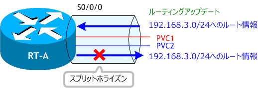
スプリットホライズンとは、あるルータから来た経路情報をそのルータに送り返さないという機能で、RIP や EIGRP のようなディスタンスベクターの特徴を持つルーティングプロトコルで動作します。スプリットホライズンが機能していると、ルーティングアップデートを特定のインターフェイスから送信する時に、そのインターフェイスで受信したルート情報を外して送信します。
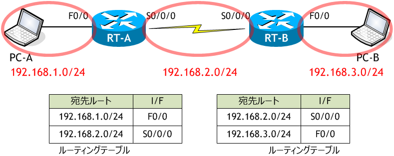
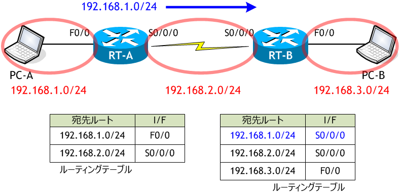
最初は、各ルータのルーティングテーブルには、直接接続したネットワークのものしかありません。
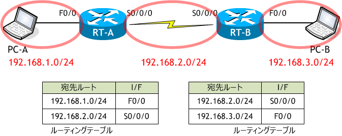
例えば RIPv2 を有効にすると、RT-A から RT-B 方向に、RT-A のルーティングテーブルにある 192.168.1.0/24 のルート情報がアップデートとして送信されます。これを受けった RT-B は自身のルーティングテーブルにこのルート情報を追加します。(192.168.2.0/24 のルート情報は RT-A の出力インターフェイスである S0/0/0 のネットワークなので、RT-A の S0/0/0 からは出力されません。)
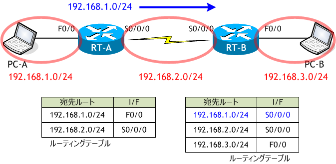
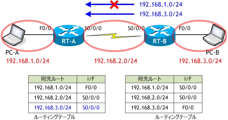
次に RT-B から RT-A 方向へのアップデートの送信です。RT-B のルーティングテーブルには 192.168.1.0/24、192.168.2.0/24、192.168.3.0/24 の3つルート情報がありますが、192.168.2.0/24 はアップデートを送信しようとしているインターフェイス S0/0/0 のネットワークであるためもともと送信されません。また、192.168.1.0/24 は RT-B の S0/0/0 で受信したアップデート (RT-A から受信したアップデート) により学習し RT-B のルーティングテーブルに載ったルート情報であるため、スプリットホライズンにより S0/0/0 インターフェイスからは出力されません。したがって、192.168.3.0/24 のルート情報のみ RT-A 方向に送信されます。これを受けった RT-A は自身のルーティングテーブルにこのルート情報を追加します。

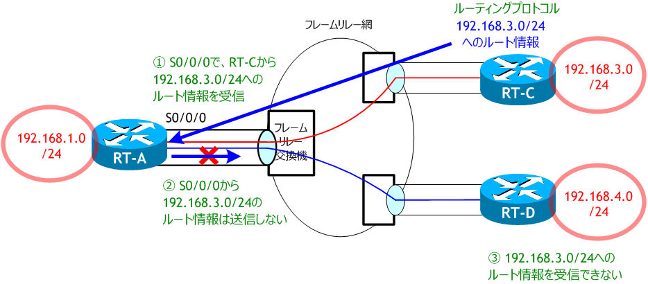
スプリットホライズンはルーティングループを防ぐための手法で、非常に重要な機能ですが、フレームリレーのハブ&スポークネットワークでは今回のように、必要なアップデートを受信できないという問題が発生します。

スプリットホライズンは、物理インターフェイスやサブインターフェイス単位で機能しますので、
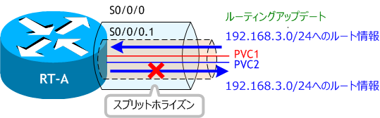
サブインターフェイスを PVC 毎に分ける (ポイントツーポイント・サブインターフェイス) ようにすれば、スプリットホライズンの影響はありません。

フレームリレーでスプリットホライズンの問題を回避するには
1) スプリットホライズンを無効にする
2) PVC 毎にサブインターフェイスを分ける (ポイントツーポイント・サブインターフェイス)
3) フレームリレーネットワークをフルメッシュにする
などがありますが、スプリットホライズンを無効にすると、ルーティングループの問題が発生する可能性があります。また、ネットワークをフルメッシュにするとコストが大幅に上がります。
スプリットホライズンとは、あるルータから来た経路情報をそのルータに送り返さないという機能で、RIP や EIGRP のようなディスタンスベクターの特徴を持つルーティングプロトコルで動作します。スプリットホライズンが機能していると、ルーティングアップデートを特定のインターフェイスから送信する時に、そのインターフェイスで受信したルート情報を外して送信します。
最初は、各ルータのルーティングテーブルには、直接接続したネットワークのものしかありません。
例えば RIPv2 を有効にすると、RT-A から RT-B 方向に、RT-A のルーティングテーブルにある 192.168.1.0/24 のルート情報がアップデートとして送信されます。これを受けった RT-B は自身のルーティングテーブルにこのルート情報を追加します。(192.168.2.0/24 のルート情報は RT-A の出力インターフェイスである S0/0/0 のネットワークなので、RT-A の S0/0/0 からは出力されません。)
次に RT-B から RT-A 方向へのアップデートの送信です。RT-B のルーティングテーブルには 192.168.1.0/24、192.168.2.0/24、192.168.3.0/24 の3つルート情報がありますが、192.168.2.0/24 はアップデートを送信しようとしているインターフェイス S0/0/0 のネットワークであるためもともと送信されません。また、192.168.1.0/24 は RT-B の S0/0/0 で受信したアップデート (RT-A から受信したアップデート) により学習し RT-B のルーティングテーブルに載ったルート情報であるため、スプリットホライズンにより S0/0/0 インターフェイスからは出力されません。したがって、192.168.3.0/24 のルート情報のみ RT-A 方向に送信されます。これを受けった RT-A は自身のルーティングテーブルにこのルート情報を追加します。
スプリットホライズンはルーティングループを防ぐための手法で、非常に重要な機能ですが、フレームリレーのハブ&スポークネットワークでは今回のように、必要なアップデートを受信できないという問題が発生します。
スプリットホライズンは、物理インターフェイスやサブインターフェイス単位で機能しますので、
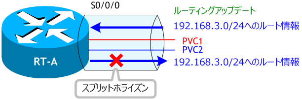

サブインターフェイスを PVC 毎に分ける (ポイントツーポイント・サブインターフェイス) ようにすれば、スプリットホライズンの影響はありません。

フレームリレーでスプリットホライズンの問題を回避するには
1) スプリットホライズンを無効にする
2) PVC 毎にサブインターフェイスを分ける (ポイントツーポイント・サブインターフェイス)
3) フレームリレーネットワークをフルメッシュにする
などがありますが、スプリットホライズンを無効にすると、ルーティングループの問題が発生する可能性があります。また、ネットワークをフルメッシュにするとコストが大幅に上がります。