フレームリレーを設定する (ポイントツーポイント・サブインターフェイス)
ネットワーク構成図
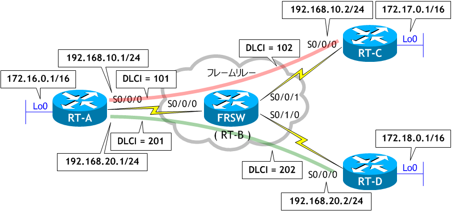
- RT-B に FRSW という名前を付け、ネットワーク構成図を参考に、フレームリレースイッチとして構成しなさい。
- RT-A の S0/0/0 をポイントツーポイント・サブインターフェイスでフレームリレーを設定しなさい。
- RT-C、RT-D の物理インターフェイス S0/0/0 にフレームリレーを設定しなさい。
- 全てのルータ間で ping を実施しなさい。
- RT-A で sh frame-relay map を実行し、フレームリレーマップを確認しなさい。
- RT-C、RT-D で sh frame-relay map を実行し、フレームリレーマップを確認しなさい。
- RT-A、RT-C、RT-D で EIGRP の設定をしなさい。
- 以下の組み合わせで ping を実施しなさい。
- RT-A、RTC、RT-D にループバックインターフェイスの設定をし、EIGRP を構成しなさい。
- RT-A、RTC、RT-D でルーティングテーブルを確認しなさい。
< RT-B >
Router# conf t
Enter configuration commands, one per line.  End with CNTL/Z.
Router(config)# host FRSW
FRSW(config)# frame-relay switching
FRSW(config)# int s0/0/0
FRSW(config-if)# description to RT-A
FRSW(config-if)# no ip address
FRSW(config-if)# clock rate 64000
FRSW(config-if)# encap frame-relay
FRSW(config-if)# frame-relay intf-type dce
FRSW(config-if)# frame-relay route 101 int s0/0/1 102
FRSW(config-if)# frame-relay route 201 int s0/1/0 202
FRSW(config-if)# no shut
FRSW(config-if)# int s0/0/1
FRSW(config-if)# description to RT-C
FRSW(config-if)# no ip address
FRSW(config-if)# clock rate 64000
FRSW(config-if)# encap frame-relay
FRSW(config-if)# frame-relay intf-type dce
FRSW(config-if)# frame-relay route 102 int s0/0/0 101
FRSW(config-if)# no shut
FRSW(config-if)# int s0/1/0
FRSW(config-if)# description to RT-D
FRSW(config-if)# no ip address
FRSW(config-if)# clock rate 64000
FRSW(config-if)# encap frame-relay
FRSW(config-if)# frame-relay intf-type dce
FRSW(config-if)# frame-relay route 202 int s0/0/0 201
FRSW(config-if)# no shut
FRSW(config-if)# ^Z
FRSW#
フレームリレースイッチの構成は CCNA の範囲外です。
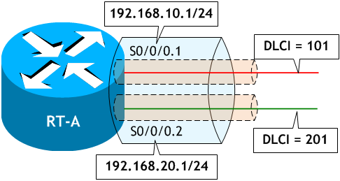
< RT-A >
Router# conf t
Enter configuration commands, one per line.  End with CNTL/Z.
Router(config)# host RT-A
RT-A(config)# int s 0/0/0
RT-A(config-if)# no ip add
RT-A(config-if)# no shut
RT-A(config-if)# encap frame-relay
RT-A(config-if)# int s 0/0/0.1 point-to-point  ← サブインターフェイスを point-to-point で構成する
RT-A(config-subif)# ip add 192.168.10.1 255.255.255.0  ← サブインターフェイスにIPアドレスを設定する
RT-A(config-subif)# frame-relay interface-dlci 101     ← サブインターフェイスで DLCI を指定する
RT-A(config-fr-dlci)# int s 0/0/0.2 point-to-point
RT-A(config-subif)# ip add 192.168.20.1 255.255.255.0
RT-A(config-subif)# frame-relay interface-dlci 201
RT-A(config-fr-dlci)# ^Z
RT-A#
ポイントツーポイント・サブインターフェイスの場合、それぞれのサブインターフェイスで使用する DLCI を frame-relay interface-dlci xxx コマンドで明示的に指定する必要があります。
< RT-C >
Router# conf t
Enter configuration commands, one per line.  End with CNTL/Z.
Router(config)# host RT-C
RT-C(config)# int s0/0/0
RT-C(config-if)# ip add 192.168.10.2 255.255.255.0
RT-C(config-if)# encap frame-relay
RT-C(config-if)# no shut
RT-C(config-if)# ^Z
RT-C#
< RT-D >
Router# conf t
Enter configuration commands, one per line.  End with CNTL/Z.
Router(config)# host RT-D
RT-D(config)# int s0/0/0
RT-D(config-if)# ip add 192.168.20.2 255.255.255.0
RT-D(config-if)# encap frame-relay
RT-D(config-if)# no shut
RT-D(config-if)# ^Z
RT-D#
RT-C と RT-D は PVC が1つなので前のシナリオと同様に物理インターフェイスにフレームリレーを設定しましたが、ポイントツーポイント・サブインターフェイスで構成することもできます。
< RT-A >
RT-A# ping 192.168.10.2  ← RT-C への ping
Type escape sequence to abort.
Sending 5, 100-byte ICMP Echos to 192.168.10.2, timeout is 2 seconds:
!!!!!  ← 成功
Success rate is 100 percent (5/5), round-trip min/avg/max = 56/58/60 ms


RT-A# ping 192.168.20.2  ← RT-D への ping
Type escape sequence to abort.
Sending 5, 100-byte ICMP Echos to 192.168.20.2, timeout is 2 seconds:
!!!!!  ← 成功
Success rate is 100 percent (5/5), round-trip min/avg/max = 56/57/60 ms
RT-A#
< RT-C >
RT-C# ping 192.168.10.1  ← RT-A の S0/0/0.1 への ping
Type escape sequence to abort.
Sending 5, 100-byte ICMP Echos to 192.168.10.1, timeout is 2 seconds:
!!!!!  ← 成功
Success rate is 100 percent (5/5), round-trip min/avg/max = 56/58/61 ms
RT-C#


RT-C# ping 192.168.20.1  ← RT-A の S0/0/0.2 への ping
Type escape sequence to abort.
Sending 5, 100-byte ICMP Echos to 192.168.20.1, timeout is 2 seconds:
.....  ← 失敗
Success rate is 0 percent (0/5)
RT-C#


RT-C# ping 192.168.20.2  ← RT-D への ping
Type escape sequence to abort.
Sending 5, 100-byte ICMP Echos to 192.168.20.2, timeout is 2 seconds:
.....  ← 失敗
Success rate is 0 percent (0/5)
RT-C#
< RT-D >
RT-D# ping 192.168.20.1  ← RT-A の S0/0/0.2 への ping
Type escape sequence to abort.
Sending 5, 100-byte ICMP Echos to 192.168.20.1, timeout is 2 seconds:
!!!!!  ← 成功
Success rate is 100 percent (5/5), round-trip min/avg/max = 56/57/61 ms
RT-D#


RT-D# ping 192.168.10.1  ← RT-A の S0/0/0.1 への ping
Type escape sequence to abort.
Sending 5, 100-byte ICMP Echos to 192.168.10.1, timeout is 2 seconds:
.....  ← 失敗
Success rate is 0 percent (0/5)
RT-D#


RT-D# ping 192.168.10.2  ← RT-C への ping
Type escape sequence to abort.
Sending 5, 100-byte ICMP Echos to 192.168.10.2, timeout is 2 seconds:
.....  ← 失敗
Success rate is 0 percent (0/5)
RT-D#
RT-C → RT-D
RT-C → RT-A の S0/0/0.2
RT-D → RT-C
RT-D → RT-A の S0/0/0.1
上記の組み合わせで ping が失敗しました。
RT-C → RT-A の S0/0/0.2
RT-D → RT-C
RT-D → RT-A の S0/0/0.1
上記の組み合わせで ping が失敗しました。
< RT-A >
RT-A# sh frame-relay map
Serial0/0/0.1 (up): point-to-point dlci, dlci 101(0x65,0x1850), broadcast ← RT-C 宛て
          status defined, active
Serial0/0/0.2 (up): point-to-point dlci, dlci 201(0xC9,0x3090), broadcast ← RT-D 宛て
          status defined, active
RT-A#
フレームリレーをポイントツーポイント・サブインターフェイスで構成した場合、通信相手と1対1で接続されるため、通信相手を特定するためのL2アドレスとL3アドレスの紐付けが必要ありません。そのため、ポイントツーポイント・サブインターフェイスでは Inverse ARP は使われません。シリアルインターフェイスをバックツーバック・ケーブルで接続し、HDLC で通信するようなイメージと思えばわかりやすいと思います。
< RT-C >
RT-C# sh frame-relay map
Serial0/0/0 (up): ip 192.168.10.1 dlci 102(0x66,0x1860), dynamic,    ← RT-A 宛て
              broadcast,
              CISCO, status defined, active
RT-C#
< RT-D >
RT-D# sh frame-relay map
Serial0/0/0 (up): ip 192.168.20.1 dlci 202(0xCA,0x30A0), dynamic,    ← RT-A 宛て
              broadcast,
              CISCO, status defined, active
RT-D#
RT-C と RT-D には、RT-A までのマップエントリしかありません。Inverse ARP では RT-C と RT-D 間で通信するためのマップエントリが自動で作成されませんので、必要なら frame-relay map を使って手動で設定する必要があります。しかし、ハブ&スポークのハブ (RT-A) をポイントツーポイント・サブインターフェイスで構成した場合、PVC 毎にネットワークが分かれるので、ルータで適切なルーティングの設定さえすれば通信できるようになります。
< RT-A >
RT-A# conf t
Enter configuration commands, one per line.  End with CNTL/Z.
RT-A(config)# router eigrp 1
RT-A(config-router)# net 192.168.10.0
RT-A(config-router)# net 192.168.20.0
RT-A(config-router)# ^Z
RT-A#
< RT-C >
RT-C# conf t
Enter configuration commands, one per line.  End with CNTL/Z.
RT-C(config)# router eigrp 1
RT-C(config-router)# net 192.168.10.0
RT-C(config-router)# ^Z
RT-C#
< RT-D >
RT-D# conf t
Enter configuration commands, one per line.  End with CNTL/Z.
RT-D(config)# router eigrp 1
RT-D(config-router)# net 192.168.20.0
RT-D(config-router)# ^Z
RT-D#
RT-C → RT-D
RT-C → RT-A の S0/0/0.2
RT-D → RT-C
RT-D → RT-A の S0/0/0.1
RT-C → RT-A の S0/0/0.2
RT-D → RT-C
RT-D → RT-A の S0/0/0.1
< RT-C → RT-D >
RT-C# ping 192.168.20.2
Type escape sequence to abort.
Sending 5, 100-byte ICMP Echos to 192.168.20.2, timeout is 2 seconds:
!!!!!  ← 成功
Success rate is 100 percent (5/5), round-trip min/avg/max = 112/114/116 ms
RT-C#
< RT-C → RT-A の S0/0/0.2 >
RT-C# ping 192.168.20.1
Type escape sequence to abort.
Sending 5, 100-byte ICMP Echos to 192.168.20.1, timeout is 2 seconds:
!!!!!  ← 成功
Success rate is 100 percent (5/5), round-trip min/avg/max = 56/58/60 ms
RT-C#
< RT-D → RT-C >
RT-D# ping 192.168.10.2
Type escape sequence to abort.
Sending 5, 100-byte ICMP Echos to 192.168.10.2, timeout is 2 seconds:
!!!!!  ← 成功
Success rate is 100 percent (5/5), round-trip min/avg/max = 112/114/117 ms
RT-D#
< RT-D → RT-A の S0/0/0.1 >
RT-D# ping 192.168.10.1
Type escape sequence to abort.
Sending 5, 100-byte ICMP Echos to 192.168.10.1, timeout is 2 seconds:
!!!!!  ← 成功
Success rate is 100 percent (5/5), round-trip min/avg/max = 56/57/60 ms
RT-D#
EIGRP を設定したことにより全てのルータ間で ping が成功しました。
静的なマップエントリを追加せずとも、スポーク同士の通信が可能です。
静的なマップエントリを追加せずとも、スポーク同士の通信が可能です。
< RT-A >
RT-A# conf t
Enter configuration commands, one per line.  End with CNTL/Z.
RT-A(config)# int lo0
RT-A(config-if)# ip add 172.16.0.1 255.255.0.0
RT-A(config-if)# router eigrp 1
RT-A(config-router)# net 172.16.0.0
RT-A(config-router)# ^Z
RT-A#
< RT-C >
RT-C# conf t
Enter configuration commands, one per line.  End with CNTL/Z.
RT-C(config)# int lo0
RT-C(config-if)# ip add 172.17.0.1 255.255.0.0
RT-C(config-if)# router eigrp 1
RT-C(config-router)# net 172.17.0.0
RT-C(config-router)# ^Z
RT-C#
< RT-D >
RT-D# conf t
Enter configuration commands, one per line.  End with CNTL/Z.
RT-D(config)# int lo0
RT-D(config-if)# ip add 172.18.0.1 255.255.0.0
RT-D(config)# router eigrp 1
RT-D(config-router)# net 172.18.0.0
RT-D(config-router)# ^Z
RT-D#
< RT-A >
RT-A# sh ip route eigrp | begin Gateway
Gateway of last resort is not set

D     172.17.0.0/16 [90/2297856] via 192.168.10.2, 00:02:37, Serial0/0/0.1
D     172.18.0.0/16 [90/2297856] via 192.168.20.2, 00:00:08, Serial0/0/0.2
RT-A#
RT-C# sh ip route eigrp | begin Gateway
Gateway of last resort is not set

D     172.16.0.0/16 [90/2297856] via 192.168.10.1, 00:03:26, Serial0/0/0
D     172.18.0.0/16 [90/2809856] via 192.168.10.1, 00:00:57, Serial0/0/0
D     192.168.20.0/24 [90/2681856] via 192.168.10.1, 00:03:21, Serial0/0/0
RT-C#
< RT-D >
RT-D# sh ip route eigrp | begin Gateway
Gateway of last resort is not set

D     172.16.0.0/16 [90/2297856] via 192.168.20.1, 00:01:17, Serial0/0/0
D     172.17.0.0/16 [90/2809856] via 192.168.20.1, 00:01:17, Serial0/0/0
D     192.168.10.0/24 [90/2681856] via 192.168.20.1, 00:01:17, Serial0/0/0
RT-D#
RT-A でスプリットホライズンを無効にしてはいませんが、EIGRP で適切なルート情報を取得しています。
ポイントツーポイント・サブインターフェイスの場合、PVC 毎にネットワークが分離されますのでスプリットホライズンの影響は受けません。
ポイントツーポイント・サブインターフェイスの場合、PVC 毎にネットワークが分離されますのでスプリットホライズンの影響は受けません。