TAによる専用線接続とISDNバックアップ (CCNA試験範囲外)
ISDN は、CCNA の試験範囲外ですが、バックアップ回線の使い方の参考になるため載せています。実際にこのシナリオに従ってやるのではなく、参考程度に見ておくといいと思います。
ネットワーク構成図
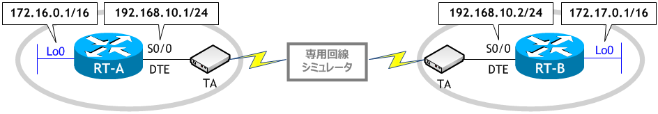
- RT-A、RT-B をネットワーク構成図に示す通り設定しなさい。ただし、ルーティングの設定には RIP を使用する。
- 拡張 ping を使い、ループバックインターフェイス同士で疎通確認を行いなさい。
- RT-A と RT-B が ISDN 回線を使って接続できるように DDR の設定をしなさい。
ISDN スイッチタイプは ntt で、インタレスティングパケットは全IPパケットとする。 - RT-A から RT-B に ping を実行した後、どのルートを使ってパケットが転送されているか traceroute を使って確認しなさい。
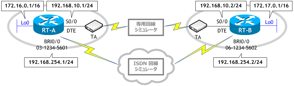
- RT-A と RT-B で ルーティングテーブルを確認しなさい。
- RT-A と RT-B で、ISDN 回線のアドミニストレーティブディスタンス値を 130 に設定しなさい。
- RT-A から RT-B に traceroute を実施しなさい。
- RT-A と RT-B で ルーティングテーブルを確認しなさい。
- 専用回線をダウンさせなさい。(専用回線シミュレータに接続しているケーブルを抜きます)
- RT-A から RT-B に ping を実行した後、どのルートを使ってパケットが転送されているか traceroute を使って確認しなさい。
- RT-A と RT-B で ルーティングテーブルを確認しなさい。
< RT-A >
Router# conf t
Enter configuration commands, one per line.  End with CNTL/Z.
Router(config)# host RT-A
RT-A(config)# int lo0
RT-A(config-if)# ip add 172.16.0.1 255.255.0.0
RT-A(config-if)# int s0/0
RT-A(config-if)# ip add 192.168.10.1 255.255.255.0
RT-A(config-if)# no shut
RT-A(config-if)# router rip
RT-A(config-router)# net 172.16.0.0
RT-A(config-router)# net 192.168.10.0
RT-A(config-router)# ^Z
RT-A#
< RT-B >
Router# conf t
Enter configuration commands, one per line.  End with CNTL/Z.
Router(config)# host RT-B
RT-B(config)# int lo0
RT-B(config-if)# ip add 172.17.0.1 255.255.0.0
RT-B(config)# int s0/0
RT-B(config-if)# ip add 192.168.10.2 255.255.255.0
RT-B(config-if)# no shut
RT-B(config-if)# router rip
RT-B(config-router)# net 172.17.0.0
RT-B(config-router)# net 192.168.10.0
RT-B(config-if)# ^Z
RT-B#
クロックの供給は回線側から行うので、RT-A、RT-B の S0/0 はともに DTE で、clock rate の設定は必要ありません。
< RT-A >
RT-A# ping 172.17.0.1 source 172.16.0.1  ← 宛先に相手先の lo0 のIPアドレスを、送信元に自身の lo0 のIPアドレスを指定
Type escape sequence to abort.
Sending 5, 100-byte ICMP Echos to 172.17.0.1, timeout is 2 seconds:
!!!!!  ← 成功
Success rate is 100 percent (5/5), round-trip min/avg/max = 32/32/32 ms
RT-A#
< RT-B >
RT-B# ping 172.16.0.1 source 172.17.0.1  ← 宛先に相手先の lo0 のIPアドレスを、送信元に自身の lo0 のIPアドレスを指定
Type escape sequence to abort.
Sending 5, 100-byte ICMP Echos to 172.16.0.1, timeout is 2 seconds:
!!!!!  ← 成功
Success rate is 100 percent (5/5), round-trip min/avg/max = 32/32/32 ms
RT-B#
お互いに ping が成功します。
ネットワークに ISDN バックアップを追加します。
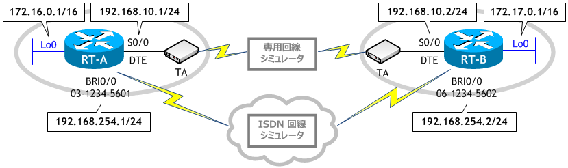
< RT-A >
RT-A# conf t
Enter configuration commands, one per line.  End with CNTL/Z.
RT-A(config)# isdn switch-type ntt
RT-A(config)# ip route 172.17.0.0 255.255.0.0 192.168.254.2
RT-A(config)# dialer-list 1 protocol ip permit
RT-A(config)# int bri0/0
RT-A(config-if)# ip add 192.168.254.1 255.255.255.0
RT-A(config-if)# encapsulation ppp
RT-A(config-if)# dialer idle-timeout 60
RT-A(config-if)# dialer map ip 192.168.254.2 name RT-B 0612345602
RT-A(config-if)# dialer-group 1
RT-A(config-if)# no shut
RT-A(config-if)# ^Z
RT-A#
< RT-B >
RT-B# conf t
Enter configuration commands, one per line.  End with CNTL/Z.
RT-B(config)# isdn switch-type ntt
RT-B(config)# ip route 172.16.0.0 255.255.0.0 192.168.254.1
RT-B(config)# dialer-list 1 protocol ip permit
RT-B(config)# int bri0/0
RT-B(config-if)# ip add 192.168.254.2 255.255.255.0
RT-B(config-if)# encapsulation ppp
RT-B(config-if)# dialer idle-timeout 60
RT-B(config-if)# dialer map ip 192.168.254.1 name RT-A 0312345601
RT-B(config-if)# dialer-group 1
RT-B(config-if)# no shut
RT-B(config-if)# ^Z
RT-B#
< RT-A >
RT-A# ping 172.17.0.1
Type escape sequence to abort.
Sending 5, 100-byte ICMP Echos to 172.17.0.1, timeout is 2 seconds:
..!!!  ← 成功
Success rate is 60 percent (3/5), round-trip min/avg/max = 28/28/28 ms
RT-A#
RT-A# traceroute 172.17.0.1
Type escape sequence to abort.
Tracing the route to 172.17.0.1

1  192.168.254.2 16 msec * 16 msec  ← RT-B の BRI0/0 を通過している
RT-A#
専用回線を通らずに、バックアップ用に設定した ISDN 回線を通ってしまいます。
< RT-A >
RT-A# sh ip route | begin Gateway
Gateway of last resort is not set

C    192.168.10.0/24 is directly connected, Serial0/0
S    172.17.0.0/16 [1/0] via 192.168.254.2  ← ISDN 回線を経由するルート
C    172.16.0.0/16 is directly connected, Loopback0
C    192.168.254.0/24 is directly connected, BRI0/0
RT-A#
< RT-B >
RT-B# sh ip route | begin Gateway
Gateway of last resort is not set

C    192.168.10.0/24 is directly connected, Serial0/0
C    172.17.0.0/16 is directly connected, Loopback0
S    172.16.0.0/16 [1/0] via 192.168.254.1  ← ISDN 回線を経由するルート
C    192.168.254.0/24 is directly connected, BRI0/0
RT-B#
ISDN 回線はスタティックで設定しているため、RIP で設定した専用回線よりも優先されます。
< RT-A >
RT-A# conf t
Enter configuration commands, one per line.  End with CNTL/Z.
RT-A(config)# ip route 172.17.0.0 255.255.0.0 192.168.254.2 130  ← AD 値 130 を設定
RT-A(config)# ^Z
RT-A#
< RT-B >
RT-B# conf t
Enter configuration commands, one per line.  End with CNTL/Z.
RT-B(config)# ip route 172.16.0.0 255.255.0.0 192.168.254.1 130  ← AD 値 130 を設定
RT-B(config)# ^Z
RT-B#
< RT-A >
RT-A# traceroute 172.17.0.1
Type escape sequence to abort.
Tracing the route to 172.17.0.1

1  192.168.10.2 16 msec 16 msec *  ← RT-B の S0/0 を通過している
RT-A#
< RT-A >
RT-A# sh ip route | begin Gateway
Gateway of last resort is not set

C    192.168.10.0/24 is directly connected, Serial0/0
R    172.17.0.0/16 [120/1] via 192.168.10.2, 00:00:07, Serial0/0  ← 専用回線を経由するルート
C    172.16.0.0/16 is directly connected, Loopback0
C    192.168.254.0/24 is directly connected, BRI0/0
RT-A#
< RT-B >
RT-B# sh ip route | begin Gateway
Gateway of last resort is not set

C    192.168.10.0/24 is directly connected, Serial0/0
C    172.17.0.0/16 is directly connected, Loopback0
R    172.16.0.0/16 [120/1] via 192.168.10.1, 00:00:06, Serial0/0  ← 専用回線を経由するルート
C    192.168.254.0/24 is directly connected, BRI0/0
RT-B#
ISDN 回線はスタティックルートで設定したため AD 値はデフォルトで 1 になっています。
専用回線は RIP で設定したため AD 値は 120 になっています。
ISDN 回線は専用回線のバックアップルートとして使用したいため、AD 値を RIP よりも高い値にする必要があります。
今回 ISDN 回線の AD値を 130 に設定したことにより、専用回線が優先されました。
このような手法をフローティングスタティックルートと呼びます。
専用回線は RIP で設定したため AD 値は 120 になっています。
ISDN 回線は専用回線のバックアップルートとして使用したいため、AD 値を RIP よりも高い値にする必要があります。
今回 ISDN 回線の AD値を 130 に設定したことにより、専用回線が優先されました。
このような手法をフローティングスタティックルートと呼びます。

< RT-A >
RT-A# ping 172.17.0.1
Type escape sequence to abort.
Sending 5, 100-byte ICMP Echos to 172.17.0.1, timeout is 2 seconds:
..!!!  ← 成功
Success rate is 60 percent (3/5), round-trip min/avg/max = 28/28/28 ms
RT-A#
RT-A# traceroute 172.17.0.1
Type escape sequence to abort.
Tracing the route to 172.17.0.1

1  192.168.254.2 16 msec * 16 msec  ← RT-B の BRI0/0 を通過している
RT-A#
< RT-A >
RT-A# sh ip route
      ・
      ・
S    172.17.0.0/16 [130/0] via 192.168.254.2  ← ISDN 回線を経由するルート
C    172.16.0.0/16 is directly connected, Loopback0
C    192.168.254.0/24 is directly connected, BRI0/0
RT-A#
< RT-B >
RT-B# sh ip route
      ・
      ・
C    172.17.0.0/16 is directly connected, Loopback0
S    172.16.0.0/16 [130/0] via 192.168.254.1  ← ISDN 回線を経由するルート
C    192.168.254.0/24 is directly connected, BRI0/0
RT-B#
専用回線がダウンしたため、バックアップルートである ISDN 回線が使用されました。