アドミニストレーティブディスタンスを理解する
※ 前の「シナリオ」の続きとして記載しています。
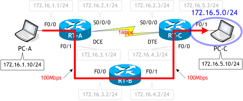
RIP では、PC-A から PC-C へのパケットは次のルートを通ることがわかりました。これは RIP のルート選択がホップ数 (通過するルータの数) で行われることに起因するものでした。
これにスタティックルートを追加し、PC-A から PC-C へのパケットが次のルートを通るように変更します。
- RT-A で、次のスタティックルートのコマンドを実行しなさい。
- RT-A、RT-B、RT-C で clear ip route * コマンドを実行しなさい。
- PC-A から RT-C へ TraceRoute を実行しなさい。
- RT-A のルーティングテーブルを表示させなさい。
- RT-A の F0/1 を shutdown させなさい。
- PC-A から PC-C へ TraceRoute を実行しなさい。
- RT-A のルーティングテーブルを表示させなさい。
< RT-A >
RT-A# conf t
Enter configuration commands, one per line.  End with CNTL/Z.
RT-A(config)# ip route 172.16.5.0 255.255.255.0 172.16.3.2
RT-A(config)# ^Z
RT-A#
< RT-A >
RT-A# clear ip route *
RT-A#
< RT-B >
RT-B# clear ip route *
RT-B#
< RT-C >
RT-C# clear ip route *
RT-C#
clear ip route * コマンドで、現在のルーティングテーブルにあるルート情報を全て消去し再学習させます。
< PC-A >
C:\> tracert 172.16.5.10

172.16.5.10 へのルートをトレースしています。経由するホップ数は最大 30 です

  1     2 ms     1 ms     1 ms  172.16.1.1   ← RT-A の E0/0
  2     1 ms     1 ms     1 ms  172.16.3.2   ← RT-B の F0/0
  3     1 ms     1 ms     1 ms  172.16.4.2   ← RT-C の F0/0
  4     4 ms     2 ms     1 ms  172.16.5.10  ← PC-C

トレースを完了しました。

C:\>
TraceRoute の結果より、PC-A から PC-C へのパケットが RT-B 経由で転送されたことがわかります。
< RT-A >
RT-A# sh ip route | begin Gateway
Gateway of last resort is not set

      172.16.0.0/16 is variably subnetted, 8 subnets, 2 masks
C        172.16.1.0/24 is directly connected, FastEthernet0/0
L        172.16.1.1/32 is directly connected, FastEthernet0/0
C        172.16.2.0/24 is directly connected, Serial0/0/0
L        172.16.2.1/32 is directly connected, Serial0/0/0
C        172.16.3.0/24 is directly connected, FastEthernet0/1
L        172.16.3.1/32 is directly connected, FastEthernet0/1
R        172.16.4.0/24 [120/1] via 172.16.3.2, 00:00:25, FastEthernet0/1
                       [120/1] via 172.16.2.3, 00:00:29, Serial0/0/0
S        172.16.5.0/24 [1/0] via 172.16.3.2
RT-A#
スタティックルートを設定する前の RT-A のルーティングテーブルにあった次の RIP ルートは
R 172.16.5.0/24 [120/1] via 172.16.2.3, 00:00:11, Serial0/0/0以下のスタティックルートに置き換わっています。
S 172.16.5.0/24 [1/0] via 172.16.3.2RIP よりもスタティックの方がアドミニストレーティブディスタンス値が小さいため、スタティックルートが採用され、RIP ルートがルーティングテーブルから削除されました。
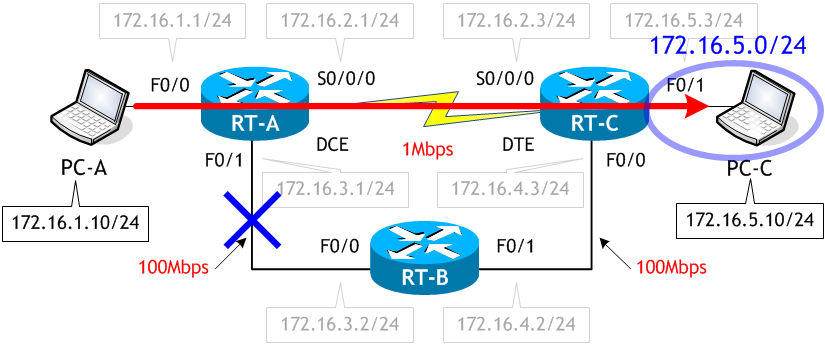
では次に、RT-A-RT-B 間をダウンさせてみましょう。
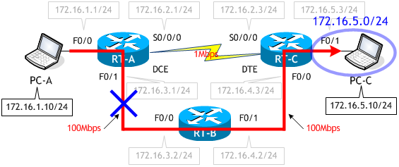
< RT-A >
RT-A# conf t
Enter configuration commands, one per line.  End with CNTL/Z.
RT-A(config)# int f0/0
RT-A(config-if)# shut
RT-A(config-if)# ^Z
RT-A#
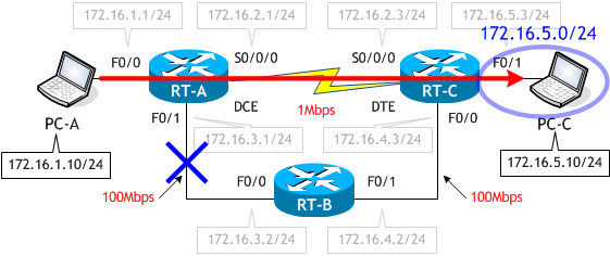
< PC-A >
C:\> tracert 172.16.5.10

172.16.5.10 へのルートをトレースしています。経由するホップ数は最大 30 です

  1     2 ms     1 ms     1 ms  172.16.1.1   ← RT-A の E0/0
  2     1 ms     1 ms     1 ms  172.16.2.3   ← RT-C の S0/0/0
  3     1 ms     1 ms     1 ms  172.16.5.10  ← PC-C

トレースを完了しました。

C:\>
TraceRoute の結果より、PC-A から PC-C へのパケットは、次のルートで転送されたことがわかります。
< RT-A >
RT-A# sh ip route | begin Gateway
Gateway of last resort is not set

      172.16.0.0/16 is variably subnetted, 6 subnets, 2 masks
C        172.16.1.0/24 is directly connected, FastEthernet0/0
L        172.16.1.1/32 is directly connected, FastEthernet0/0
C        172.16.2.0/24 is directly connected, Serial0/0/0
L        172.16.2.1/32 is directly connected, Serial0/0/0
R        172.16.4.0/24 [120/1] via 172.16.2.3, 00:00:08, Serial0/0/0
R        172.16.5.0/24 [120/1] via 172.16.2.3, 00:00:08, Serial0/0/0
RT-A#
設定したスタティックルートがなくなり、RIP ルートが復活しました。
今回、アドミニストレーティブディスタンスを理解するために、RIP ネットワークにスタッティックルートの設定を行いましたが、これはあくまで一例で、この設定のままでは PC-C → PC-A のパケットは相変わらずシリアル回線を使用しますし、ネットワークトラブルが発生した場合の回避等についても考慮していません。この点はご注意ください。