VLSMネットワークでRIPを使用する
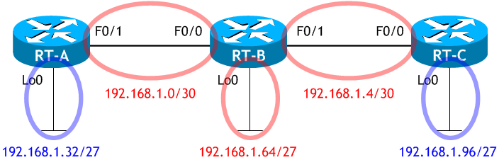
ネットワーク構成図
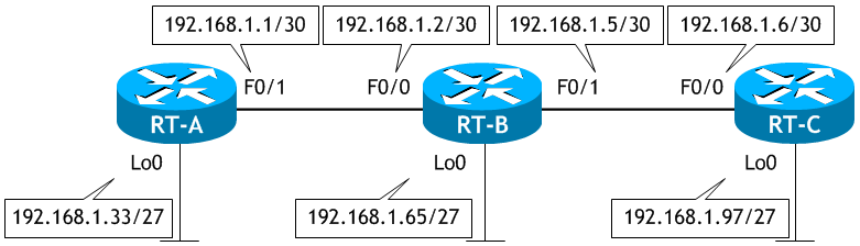
- RT-A、RT-B、RT-C をネットワーク構成図に示す通り設定し、合わせて必要な RIP の設定も行いなさい。
- Lo0 のIPアドレスを使って、RT-A から RT-B の Lo0 へ ping を実行しなさい。
- Lo0 のIPアドレスを使って、RT-A から RT-C の Lo0 へ ping を実行しなさい。
- RT-A のルーティングテーブル (RIP) を表示させなさい。
- RT-B のルーティングテーブル (RIP) を表示させなさい。
- RT-C のルーティングテーブル (RIP) を表示させなさい。
- RT-A、RT-B、RT-C で RIPv2 を有効にしなさい。
- RT-A、RT-B、RT-C のルーティングテーブルを表示させなさい。
- Lo0 のIPアドレスを使って、RT-A から RT-B の Lo0 へ ping を実行しなさい。
- Lo0 のIPアドレスを使って、RT-A から RT-C の Lo0 へ ping を実行しなさい。
< RT-A >
Router# conf t
Enter configuration commands, one per line.  End with CNTL/Z.
Router(config)# host RT-A
RT-A(config)# int lo0
RT-A(config-if)# ip add 192.168.1.33 255.255.255.224
RT-A(config-if)# int f0/1
RT-A(config-if)# ip add 192.168.1.1 255.255.255.252
RT-A(config-if)# no shut
RT-A(config-if)# router rip
RT-A(config-router)# network 192.168.1.0
RT-A(config-router)# ^Z
RT-A#
< RT-B >
Router# conf t
Enter configuration commands, one per line.  End with CNTL/Z.
Router(config)# host RT-B
RT-B(config)# int lo0
RT-B(config-if)# ip add 192.168.1.65 255.255.255.224
RT-B(config-if)# int f0/0
RT-B(config-if)# ip add 192.168.1.2 255.255.255.252
RT-B(config-if)# no shut
RT-B(config-if)# int f0/1
RT-B(config-if)# ip add 192.168.1.5 255.255.255.252
RT-B(config-if)# no shut
RT-B(config-if)# router rip
RT-B(config-router)# network 192.168.1.0
RT-B(config-router)# ^Z
RT-B#
< RT-C >
Router# conf t
Enter configuration commands, one per line.  End with CNTL/Z.
Router(config)# host RT-C
RT-C(config)# int lo0
RT-C(config-if)# ip add 192.168.1.97 255.255.255.224
RT-C(config-if)# int f0/0
RT-C(config-if)# ip add 192.168.1.6 255.255.255.252
RT-C(config-if)# no shut
RT-C(config-if)# router rip
RT-C(config-router)# network 192.168.1.0
RT-C(config-router)# ^Z
RT-C#
RT-A# ping 192.168.1.65 source 192.168.1.33  ← 192.168.1.33 が RT-A の Lo0 のIPアドレス
Type escape sequence to abort.
Sending 5, 100-byte ICMP Echos to 192.168.1.65, timeout is 2 seconds:
Packet sent with a source address of 192.168.1.33
.....
Success rate is 0 percent (0/5)
RT-A#
ping が失敗しました。
RT-A# ping 192.168.1.97 source 192.168.1.33
Type escape sequence to abort.
Sending 5, 100-byte ICMP Echos to 192.168.1.97, timeout is 2 seconds:
Packet sent with a source address of 192.168.1.33
.....
Success rate is 0 percent (0/5)
RT-A#
ping が失敗しました。
< RT-A >
RT-A# sh ip route rip | begin Gateway
Gateway of last resort is not set

      192.168.1.0/24 is variably subnetted, 5 subnets, 3 masks
R        192.168.1.4/30 [120/1] via 192.168.1.2, 00:00:11, FastEthernet0/1
RT-A#
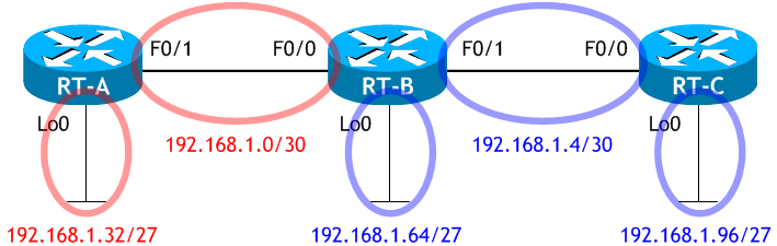
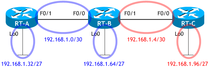
RT-A のルーティングテーブルには
192.168.1.64/27 のネットワーク (RT-B の Lo0 があるネットワーク) に行くルート情報も
192.168.1.96/27 のネットワーク (RT-C の Lo0 があるネットワーク) に行くルート情報も
ありません。
これでは、それらのネットワーク上にあるインターフェイスへの ping は失敗します。
192.168.1.64/27 のネットワーク (RT-B の Lo0 があるネットワーク) に行くルート情報も
192.168.1.96/27 のネットワーク (RT-C の Lo0 があるネットワーク) に行くルート情報も
ありません。
これでは、それらのネットワーク上にあるインターフェイスへの ping は失敗します。
< RT-B >
RT-B# sh ip route rip | begin Gateway
Gateway of last resort is not set

RT-B#
RT-B には、RIP で学習したルートが全くありません。
< RT-C >
RT-C# sh ip route rip | begin Gateway
Gateway of last resort is not set

      192.168.1.0/24 is variably subnetted, 5 subnets, 3 masks
R        192.168.1.0/30 [120/1] via 192.168.1.5, 00:00:18, FastEthernet0/0
RT-C#
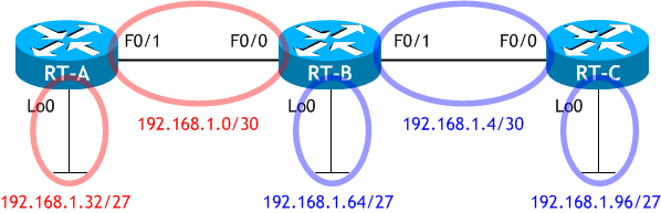
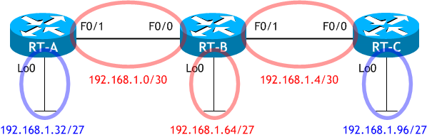
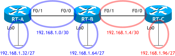
RT-C も次図に示す Blue のネットワークへ行くための RIP ルートが必要です。
今回のネットワークは 192.168.1.0 のネットワークを VLSM 化しています。
そのため、VLSM に対応したルーティングプロトコルを使う必要があります。
RIPv1 は VLSM に対応していません。
そのため、VLSM に対応したルーティングプロトコルを使う必要があります。
RIPv1 は VLSM に対応していません。
< RT-A >
RT-A# conf t
Enter configuration commands, one per line.  End with CNTL/Z.
RT-A(config)# router rip
RT-A(config-router)# version 2
RT-A(config-router)# ^Z
RT-A#
< RT-B >
RT-B# conf t
Enter configuration commands, one per line.  End with CNTL/Z.
RT-B(config)# router rip
RT-B(config-router)# version 2
RT-B(config-router)# ^Z
RT-B#
< RT-C >
RT-C# conf t
Enter configuration commands, one per line.  End with CNTL/Z.
RT-C(config)# router rip
RT-C(config-router)# version 2
RT-C(config-router)# ^Z
RT-C#
< RT-A >
RT-A# sh ip route rip | begin Gateway
Gateway of last resort is not set

      192.168.1.0/24 is variably subnetted, 7 subnets, 3 masks
R        192.168.1.4/30 [120/1] via 192.168.1.2, 00:00:10, FastEthernet0/1   ← 192.168.1.4/30 宛てのルート
R        192.168.1.64/27 [120/1] via 192.168.1.2, 00:00:10, FastEthernet0/1  ← 192.168.1.64/27 宛てのルート
R        192.168.1.96/27 [120/2] via 192.168.1.2, 00:00:07, FastEthernet0/1  ← 192.168.1.96/27 宛てのルート
RT-A#
RT-A のルーティングテーブルに
192.168.1.64/27 のネットワーク (RT-B の F0/0 があるネットワーク) に行くルート情報と
192.168.1.96/27 のネットワーク (RT-C の F0/0 があるネットワーク) に行くルート情報が
追加されました。
192.168.1.64/27 のネットワーク (RT-B の F0/0 があるネットワーク) に行くルート情報と
192.168.1.96/27 のネットワーク (RT-C の F0/0 があるネットワーク) に行くルート情報が
追加されました。
< RT-B >
RT-B# sh ip route rip | begin Gateway
Gateway of last resort is not set

      192.168.1.0/24 is variably subnetted, 8 subnets, 3 masks
R        192.168.1.32/27 [120/1] via 192.168.1.1, 00:00:26, FastEthernet0/0  ← 192.168.1.32/27 宛てのルート
R        192.168.1.96/27 [120/1] via 192.168.1.6, 00:00:14, FastEthernet0/1  ← 192.168.1.96/27 宛てのルート
RT-B#
RT-B のルーティングテーブルに
192.168.1.32/27 のネットワークに行くルート情報と
192.168.1.96/27 のネットワークに行くルート情報が
追加されました。
192.168.1.32/27 のネットワークに行くルート情報と
192.168.1.96/27 のネットワークに行くルート情報が
追加されました。
< RT-C >
RT-C# sh ip route rip | begin Gateway
Gateway of last resort is not set

      192.168.1.0/24 is variably subnetted, 7 subnets, 3 masks
R        192.168.1.0/30 [120/1] via 192.168.1.5, 00:00:03, FastEthernet0/0   ← 192.168.1.0/27 宛てのルート
R        192.168.1.32/27 [120/2] via 192.168.1.5, 00:00:03, FastEthernet0/0  ← 192.168.1.32/27 宛てのルート
R        192.168.1.64/27 [120/1] via 192.168.1.5, 00:00:03, FastEthernet0/0  ← 192.168.1.64/27 宛てのルート
RT-C#
RT-C のルーティングテーブルに
192.168.1.32/27 のネットワークに行くルート情報と
192.168.1.64/27 のネットワークに行くルート情報が
追加されました。
192.168.1.32/27 のネットワークに行くルート情報と
192.168.1.64/27 のネットワークに行くルート情報が
追加されました。
RT-A# ping 192.168.1.65 source 192.168.1.33
Type escape sequence to abort.
Sending 5, 100-byte ICMP Echos to 192.168.1.65, timeout is 2 seconds:
Packet sent with a source address of 192.168.1.33
!!!!!
Success rate is 100 percent (5/5), round-trip min/avg/max = 1/2/4 ms
RT-A#
ping が成功しました。
RT-A# ping 192.168.1.97 source 192.168.1.33
Type escape sequence to abort.
Sending 5, 100-byte ICMP Echos to 192.168.1.97, timeout is 2 seconds:
Packet sent with a source address of 192.168.1.33
!!!!!
Success rate is 100 percent (5/5), round-trip min/avg/max = 1/2/4 ms
RT-A#
ping が成功しました。