不連続サブネットワークでRIPを使用する
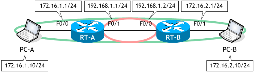
次の図は、3つのネットワークで構成されています。
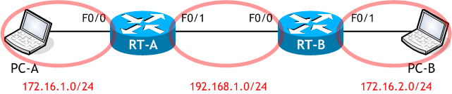
この図を、メジャーネットワークで捉えると、172.16.0.0/16 のネットワークを 192.168.1.0/24 のネットワークで分断した形になります。このような、メジャーネットワークが共通 (172.16.0.0) のサブネット (172.16.1.0/24 と 172.16.2.0/24) が物理的に連続していないネットワークを不連続サブネットネットワークと呼びます。
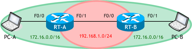
次の図を使って、不連続サブネットワークでの RIP の設定を行いたいと思います。
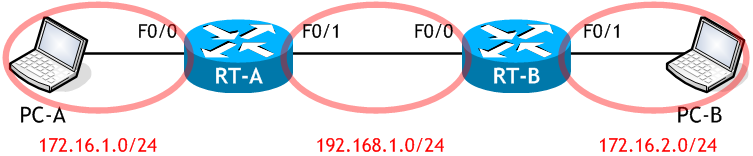
この図を、メジャーネットワークで捉えると、172.16.0.0/16 のネットワークを 192.168.1.0/24 のネットワークで分断した形になります。このような、メジャーネットワークが共通 (172.16.0.0) のサブネット (172.16.1.0/24 と 172.16.2.0/24) が物理的に連続していないネットワークを不連続サブネットネットワークと呼びます。
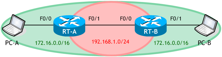
次の図を使って、不連続サブネットワークでの RIP の設定を行いたいと思います。
想定するネットワーク構成図
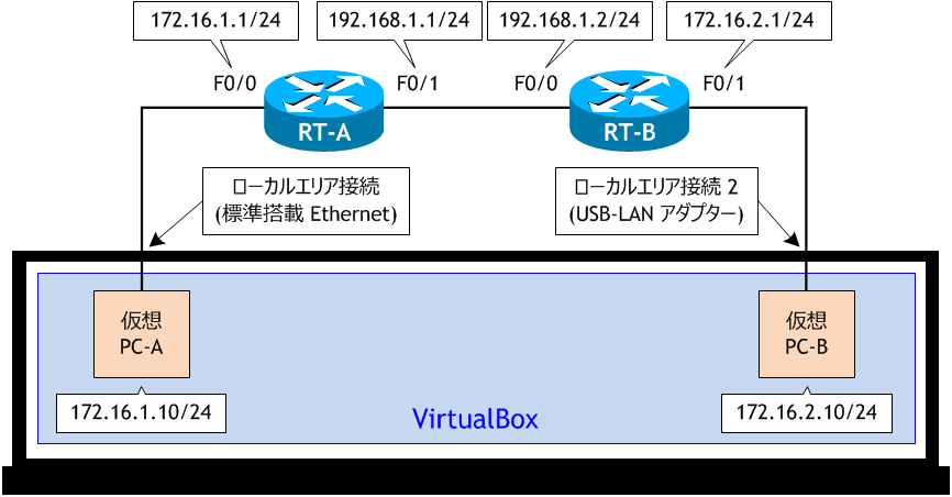
ラボ・シナリオで使用するネットワーク構成図
・物理 PC の VirtualBox 上に、PC-A、PC-B の2つの仮想 PC を構成する。・PC-A は物理 PC に標準搭載している LAN ポートを使用するように VirtualBox を設定する。
・物理 PC に USB-LAN 変換ケーブルを1つ接続し、PC-B がそれを使用するように VirtualBox を設定する。
参考 : VirtualBox のインストールと基本的な使用方法
- RT-A、RT-B をネットワーク構成図に示す通り設定し、合わせて必要な RIP の設定も行いなさい。
- PC-A、PC-B をネットワーク構成図に示す通り設定しなさい。
- PC-A から PC-B へ ping を実行しなさい。
- RT-A、RT-B のルーティングテーブル (RIP) を表示させなさい。
- RT-A、RT-B で RIPv2 を有効にしなさい。
- PC-A から PC-B へ ping を実行しなさい。
- RT-A、RT-B のルーティングテーブル (RIP) を表示させなさい。
< RT-A >
Router# conf t
Enter configuration commands, one per line.  End with CNTL/Z.
Router(config)# host RT-A
RT-A(config)# int f0/0
RT-A(config-if)# ip add 172.16.1.1 255.255.255.0
RT-A(config-if)# no shut
RT-A(config-if)# int f0/1
RT-A(config-if)# ip add 192.168.1.1 255.255.255.0
RT-A(config-if)# no shut
RT-A(config-if)# router rip
RT-A(config-router)# net 192.168.1.0
RT-A(config-router)# net 172.16.0.0
RT-A(config-router)# ^Z
RT-A#
< RT-B >
Router# conf t
Enter configuration commands, one per line.  End with CNTL/Z.
Router(config)# host RT-B
RT-B(config)# int f0/0
RT-B(config-if)# ip add 192.168.1.2 255.255.255.0
RT-B(config-if)# no shut
RT-B(config-if)# int f0/1
RT-B(config-if)# ip add 172.16.2.1 255.255.255.0
RT-B(config-if)# no shut
RT-B(config-if)# router rip
RT-B(config-router)# net 192.168.1.0
RT-B(config-router)# net 172.16.0.0
RT-B(config-router)# ^Z
RT-B#
< PC-A >
C:\> netsh interface ipv4 set address "イーサネット" static 172.16.1.10 255.255.255.0 172.16.1.1

C:\> ipconfig

Windows IP 構成

イーサネット アダプター イーサネット:

   接続固有の DNS サフィックス . . . . .:
   IPv4 アドレス . . . . . . . . . . . .: 172.16.1.10
   サブネット マスク . . . . . . . . . .: 255.255.255.0
   デフォルト ゲートウェイ . . . . . . .: 172.16.1.1

C:\>
< PC-B >
C:\> netsh interface ipv4 set address "イーサネット" static 172.16.2.10 255.255.255.0 172.16.2.1

C:\> ipconfig

Windows IP 構成

イーサネット アダプター イーサネット:

   接続固有の DNS サフィックス . . . . .:
   IPv4 アドレス . . . . . . . . . . . .: 172.16.2.10
   サブネット マスク . . . . . . . . . .: 255.255.255.0
   デフォルト ゲートウェイ . . . . . . .: 172.16.2.1

C:\>
全ての PC は ping 着信許可の設定を行っているものとします。
< PC-A >
C:\> ping 172.16.2.10

172.16.2.10 に ping を送信しています 32 バイトのデータ:
172.16.1.1 からの応答: 宛先ホストに到達できません。
172.16.1.1 からの応答: 宛先ホストに到達できません。
172.16.1.1 からの応答: 宛先ホストに到達できません。
172.16.1.1 からの応答: 宛先ホストに到達できません。

172.16.2.10 の ping 統計:
    パケット数: 送信 = 4、受信 = 4、損失 = 0 (0% の損失)、

C:\>
ping が失敗しました。
< RT-A >
RT-A# sh ip route rip | begin Gateway
Gateway of last resort is not set

RT-A#
< RT-B >
RT-B# sh ip route rip | begin Gateway
Gateway of last resort is not set

RT-B#
両ルータとも RIP により学習したルートがありません。
RIPv1 は不連続サブネットワークには対応していません。
不連続サブネットワークに対応したルーティングプロトコルを使う必要があります。
不連続サブネットワークに対応したルーティングプロトコルを使う必要があります。
< RT-A >
RT-A# conf t
Enter configuration commands, one per line.  End with CNTL/Z.
RT-A(config)# router rip
RT-A(config-router)# version 2
RT-A(config-router)# ^Z
RT-A#
< RT-B >
RT-B# conf t
Enter configuration commands, one per line.  End with CNTL/Z.
RT-B(config)# router rip
RT-B(config-router)# version 2
RT-B(config-router)# ^Z
RT-B#
< PC-A >
C:\> ping 172.16.2.10

172.16.2.10 に ping を送信しています 32 バイトのデータ:
172.16.2.10 からの応答: バイト数 =32 時間 =3ms TTL=126
172.16.2.10 からの応答: バイト数 =32 時間 =2ms TTL=126
172.16.2.10 からの応答: バイト数 =32 時間 =2ms TTL=126
172.16.2.10 からの応答: バイト数 =32 時間 =1ms TTL=126

172.16.2.10 の ping 統計:
    パケット数: 送信 = 4、受信 = 4、損失 = 0 (0% の損失)、
ラウンド トリップの概算時間 (ミリ秒):
    最小 = 1ms、最大 = 3ms、平均 = 2ms

C:\>
ping が成功しました。
< RT-A >
RT-A# sh ip route rip | begin Gateway
Gateway of last resort is not set

      172.16.0.0/16 is variably subnetted, 3 subnets, 3 masks
R        172.16.0.0/16 [120/1] via 192.168.1.2, 00:00:01, FastEthernet0/1   ← 172.16.0.0/16 宛てのルート
RT-A#
< RT-B >
RT-B# sh ip route rip | begin Gateway
Gateway of last resort is not set

      172.16.0.0/16 is variably subnetted, 3 subnets, 3 masks
R        172.16.0.0/16 [120/1] via 192.168.1.1, 00:00:22, FastEthernet0/0   ← 172.16.0.0/16 宛てのルート
RT-B#
RIP ルートがでてきました。
ただし、現時点では、172.16.1.0/24 や 172.16.2.0/24 のようなサブネット単位のルートではなく、
クラスで集約されたルート 172.16.0.0/16 です。
ただし、現時点では、172.16.1.0/24 や 172.16.2.0/24 のようなサブネット単位のルートではなく、
クラスで集約されたルート 172.16.0.0/16 です。
※ 次の「シナリオ」に続きます。